


10
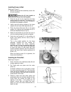
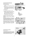
Installing Fence to Bed
Referring to Figure 5:
1. Before moving the fence assembly, secure the
tilt lock handle (K).
Secure the tilt lock handle to
avoid personal injury from moving parts.
2. Place the key (F) into the machined slot of the
fence support (G) as shown. The spring pin (E)
should go into the hole in the slot. The key (F)
should be firmly seated in the slot.
3. Lightly coat the mating surfaces of the fence
support (G) and fence slide base (B) with oil.
4. Place the fence slide base (B) on the fence
support (G), aligning the machined slot (D) in
the fence slide base with the key (F).
5. Attach the flat washer (H) and two hex nuts (J)
on to the locking screw (A) but do not tighten.
6. Orient the lock handle (C) in the position as
shown; then tighten the hex nuts (J) with a
19mm wrench.
This is the locked position for the fence
assembly. Rotating the lock handle (C)
clockwise loosens the fence assembly,
permitting you to slide the assembly back and
forth. The hex nuts may need to be readjusted
to allow the fence to slide back and forth
(handle clockwise position) and still sufficiently
secure the fence (lock handle positioned as
shown in C).
When the locking screw (A) is tightened, the
fence should be secure.
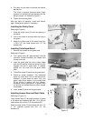
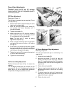
Installing the Drive Belt
Referring to Figure 6:
1. Place V-belt (A) onto cutterhead pulley (B) and
through opening in stand.
2. Pull V-belt down and place onto the motor
pulley (C).
If the belt is difficult to roll on the pulley, loosen
the motor mounting screws (D). Then raise the
motor as high as possible and mount the belt
on to both pulleys. Allow the motor to drop and
create tension on the belt.
3. Check to make sure that motor pulley and
cutterhead pulley are vertically aligned and the
V-belt does not contact the sides of the
opening in the base. If the pulleys are not
aligned, remove belt and adjust the motor
pulley in or out on the motor shaft and then re-
attach the belt.
Figure 5
Figure 6
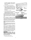
Figure 7