


14
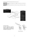
Fence Stop Adjustments
Periodically check the 90° and 45° backward
(135°) tilt accuracy of the fence with an angle
measuring device, such as an adjustable square or
machinist’s protractor.
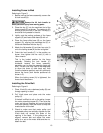
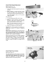
90º Stop Adjustment
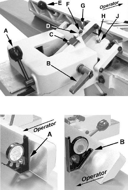
Referring to Figure 14:
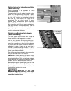
The 90º stop is controlled by the stop bolt (F) and
the stop block (C).
1. Set the infeed table to approximately the same
height as the outfeed table.
2. Move the fence by releasing lock handle (A)
and pushing the fence assembly until it
overlaps the tables.
3. Tighten lock handle (A).
4. Adjust the fence to a 90º angle by releasing
lock handle (B), pulling up on the fence handle
E), and tightening the lock handle (B).
Note: The stop bolt (F) should be resting
against the stop block (C).
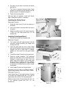
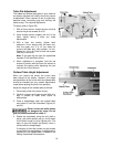
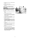
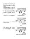
5. Place an angle measuring device on the table
and against the fence to confirm a 90º setting
(A, Fig. 15).
6. If the fence is not square to the table, release
the lock handle (B), loosen the lock nut (D) that
secures the stop bolt (F), and turn the stop bolt
until the fence is square to the table.
7. Tighten the lock nut (D) to secure the stop bolt
(F) which retains the setting.
8. Tighten the lock handle (B).
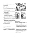
45º Forward Stop Adjustment
Position the fence tilt lever (E, Fig. 14) toward the
operator.
The 45 degree forward stop is controlled by the
cap screw (G, Fig. 14). The adjustment is done the
same way as for the 90 degree stop adjustment
except that a 45 degree protractor is used.
Figure 14
Figure 15
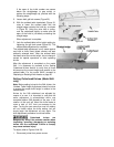
45º Fence Backward Stop Adjustment
Referring to Figure 14:
The 45º fence backward stop is controlled by the
stop bolt (H).
1. Loosen the lock handle (B).
2. Move the stop block (C) out of the way and
position the fence at the 135º angle; fence tilt
lever (E) is positioned away from the operator
as shown. Make sure the fence sits against the
stop bolt (H).
3. Tighten the lock handle (B).
4. Place an angle measuring device on the table
and against the fence to confirm a 135º setting
(B, Fig. 15).
5. To adjust, loosen the lock nut (J) securing the
stop bolt (H) and turn the stop bolt until a 135º
angle of the fence is obtained.
6. Tighten the lock nut (J).