


18
2. Carefully number each blade with a marker to
make them easier to differentiate.
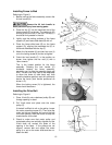
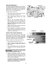
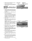
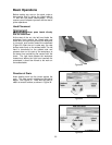
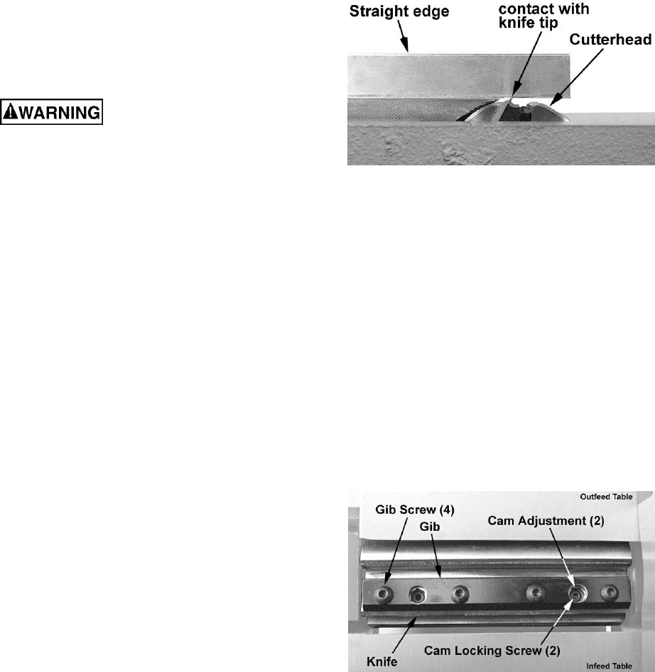
3. Place a straightedge across the outfeed table
extending it over the cutterhead towards one
end of the knife.
Cutterhead knives are
dangerously sharp. Do not grab the cutterhead
itself to rotate it! Failure to comply may cause
serious injury.
4. Rotate the cutterhead back and forth using the
drive belt or pulley, until knife number one is at
its highest point. The apex of the knife should
just barely come in contact with the
straightedge.
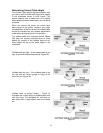
5. Move the straightedge towards the other end
of the knife and repeat step 4.
The apex of the knife at both ends of the knife
must just make contact with the straightedge. If
the apex of the knife comes below the
straightedge (a gap exists) or pushes the
straightedge up, proceed to the next step.
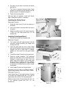
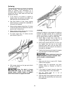
6. Using a 4mm hex wrench, slightly loosen the
four gib screws.
7. Using a 3mm hex wrench, loosen the cam
locking screws to permit adjustment of the cam
(described in the next step).
Important: Always keep the cam locking
screws snug enough so that the cam can’t
rotate freely. This is especially important for
when the cam is rotated counterclockwise
since this action will cause the cam locking
screw to loosen further.
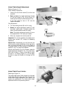
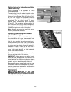
8. Using an 8mm hex wrench, adjust the cam
(see Figure 25). This is a very sensitive
adjustment. Start by rotating the cam in a
clockwise direction just a few degrees.
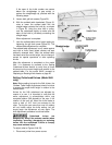
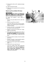
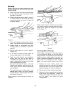
9. Next, keep the cutterhead steady by firmly
holding on to the pulley, place a piece of wood
pressed against the knife’s edge and press to
properly seat the blade.
10. Check your progress by repeating steps 4 and
5. If the knife becomes more out of adjustment,
turn the cam in the other direction.
11. The adjustment is almost complete when the
requirements described in Steps 4 and 5 are
met.
12. Next, while pressing the knife firmly against the
cam, snug the two inside gib screws that hold
the gib and knife in place. Verify that the knife
is still in adjustment (steps 4 and 5).
13. Tighten the two outside gib screws, then the
two inside gib screws.
Figure 24
Figure 25