


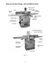
11
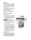
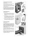
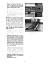
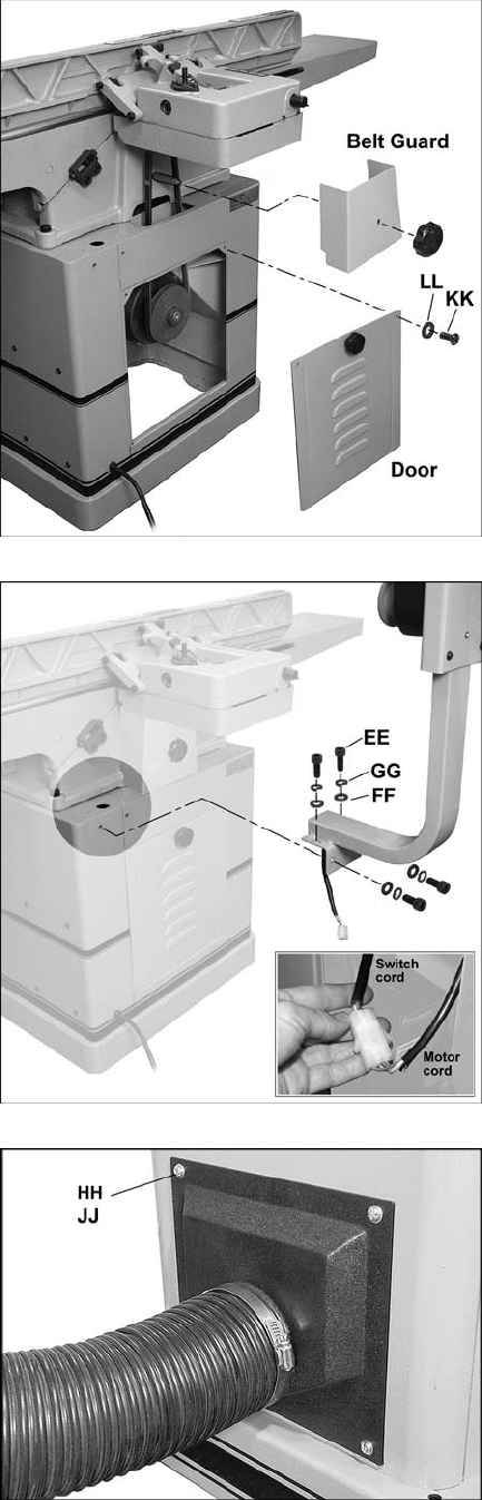
Installing Belt Guard and Door
Refer to Figure 9.
Mount the belt guard over the shaft as shown,
and install the knob to secure it in place.
Set the lip of the door over the bottom edge of
the stand opening. Rotate the door knob to hold
the door to the stand.
NOTE: When the jointer is being operated, the
two M6 pan head screws (KK) and M6 flat
washers (LL) should be installed to fully secure
the door. At this moment, however, leave these
screws off until the switch has been installed.
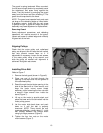
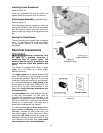
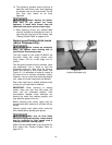
Installing Switch Arm
Refer to Figure 10.
1. Align the holes of the switch arm with the
holes on the jointer stand, while slipping the
electrical cord down through the larger hole
in the stand.
2. Secure the switch arm with four 5/16”-18 x
3/4” socket head cap screws (EE), four
5/16” lock washers (GG), and four 5/16” flat
washers (FF), using a 6mm hex wrench.
3. Open the stand door, and join the
connectors of the switch cord and motor
cord, as shown in the detail in Figure 10.
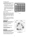
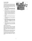
Installing Dust Chute
Refer to Figure 11.
It is strongly recommended that a dust collection
system (not provided) be connected to the
jointer. It will help keep your shop clean, and
reduce the risk of health problems due to wood
dust. The dust collector should have sufficient
capacity for this size jointer. Visit our website at
www.powermatic.com to see a range of
available dust collection units.
Place the dust chute over the opening in the
jointer stand, and secure with four 1/4”-20 x 1/2”
pan head screws (HH) and four 1/4” flat washers
(JJ).
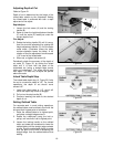
Connect a suitable dust collection hose to the
dust chute on the jointer and secure it with a
hose clamp. NOTE: Dryer vent hose is not
acceptable for this purpose.
Figure 9
Figure 10
Figure 11
(hose and clamp not provided)