


6
RECEIVING THE SANDER
Remove sander from its crate. Check for damage
and ensure all parts are intact. Any damage should
be reported immediately to your distributor and
shipping agent. Before assembling, read the
manual thoroughly, familiarizing yourself with cor-
rect assembly and maintenance procedures and
proper safety precautions.
Contents:
1 Sander
2 Work tables
1 Dust chute
1 Steel platen
1 Hardware bag containing 1 phillips screwdriver,
1 open-end wrench, 4 allen wrenches
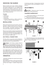
INSTALLATION
Remove the bolts securing the sander to the ship-
ping base. Install the machine on firm, level ground
with 5/16" lag bolts through the holes in the bot-
tom of the base. Use shims if necessary to level
the machine before tightening the lag bolts.
Remove any protective coating from exposed metal
surfaces with a soft cloth moistened with a good com-
mercial solvent. DO NOT use acetone, gasoline, lac-
quer thinner or any type of flammable solvent. Do
not use solvents on plastic parts.
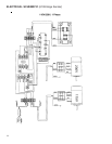
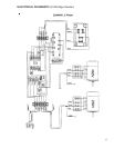
ELECTRICAL CONNECTIONS
Wire the sander to a grounded, metal-enclosed wir-
ing system in accordance with the requirements of
the National Electric Code (ANSI/NFPA70).
WARNING: ELECTRICAL WIRING SHOULD
BE DONE BY A QUALIFIED ELECTRICIAN. THE
MACHINE MUST BE PROPERLY GROUNDED TO
HELP AVOID ELECTRIC SHOCK AND ASSOCI-
ATED HAZARDS INCLUDING POSSIBLE DEATH.
If your edge sander is 3-phase, there is a four con-
ductor power source cable. If single-phase, it has a
three conductor power source cable. On both mod-
els, the ground conductor is green or yellow & green.
NEVER connect the green wire to a live terminal.
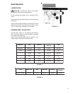
OPERATION
The sander is equipped with a push-button magnetic
control system.
When starting the machine, make sure the rotational
direction is correct. If it is not, the power connection
will have to be changed: If 3-phase, change any two
of the three power leads. If single-phase, check the
motor connection (refer to wiring diagram in connec-
tion box.)
ADJUSTMENTS
CAUTION: Disconnect sander from power
source before making adjustments.
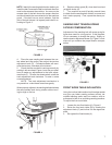
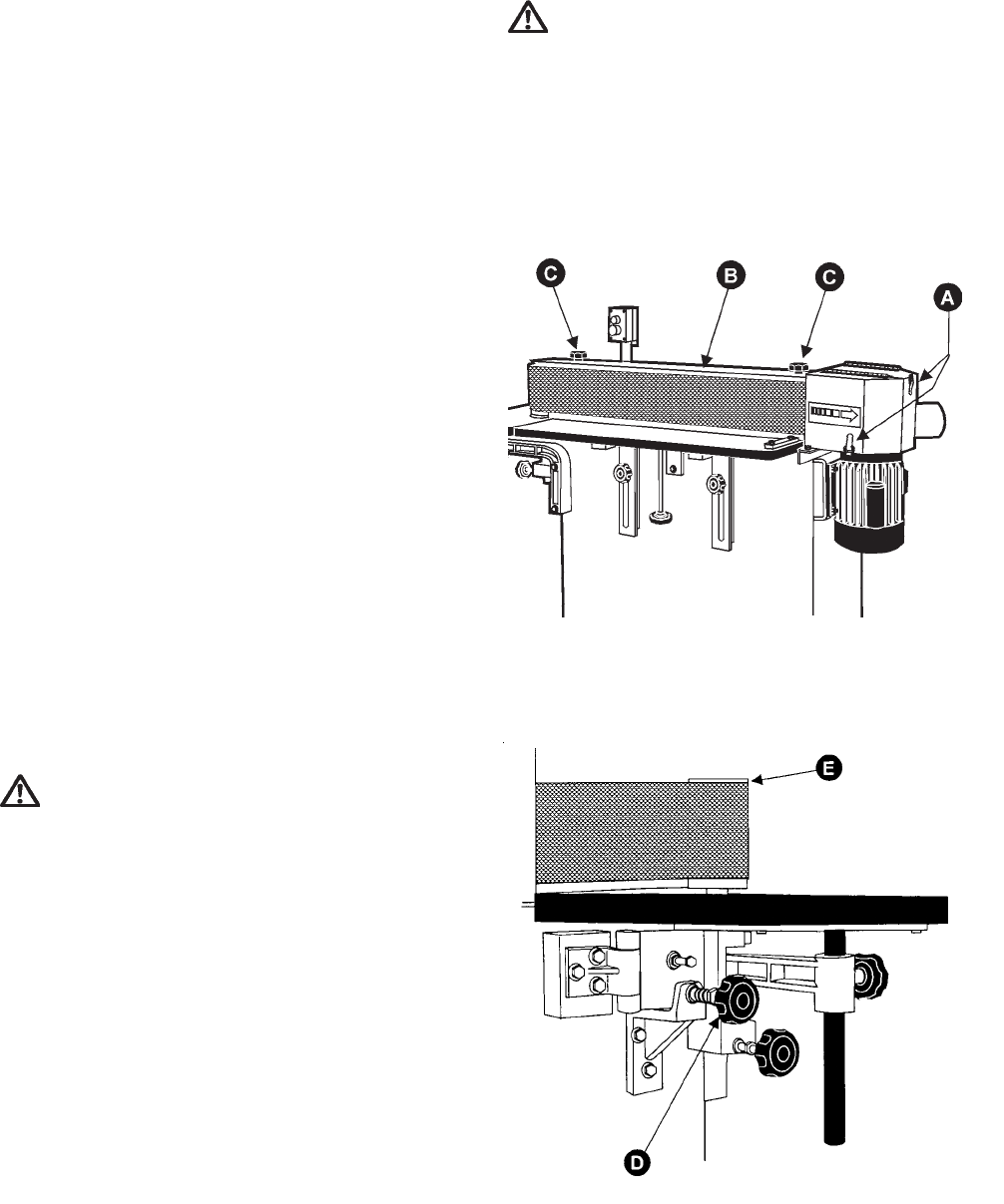
CHANGING SANDING BELT
1. Loosen the two latches (A), on the dust chute,
and open the dust hood, Figure 1.
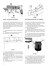
2. Remove the sanding belt safety guard (B) by
removing the two knobs (C) which are on the guard.
FIGURE 1
3. Rotate the sanding belt tension adjustment knob
(D) clockwise to release idler pulley device (E). See
Figure 2. Remove the old belt.
FIGURE 2