


7
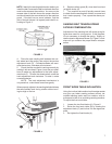
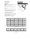
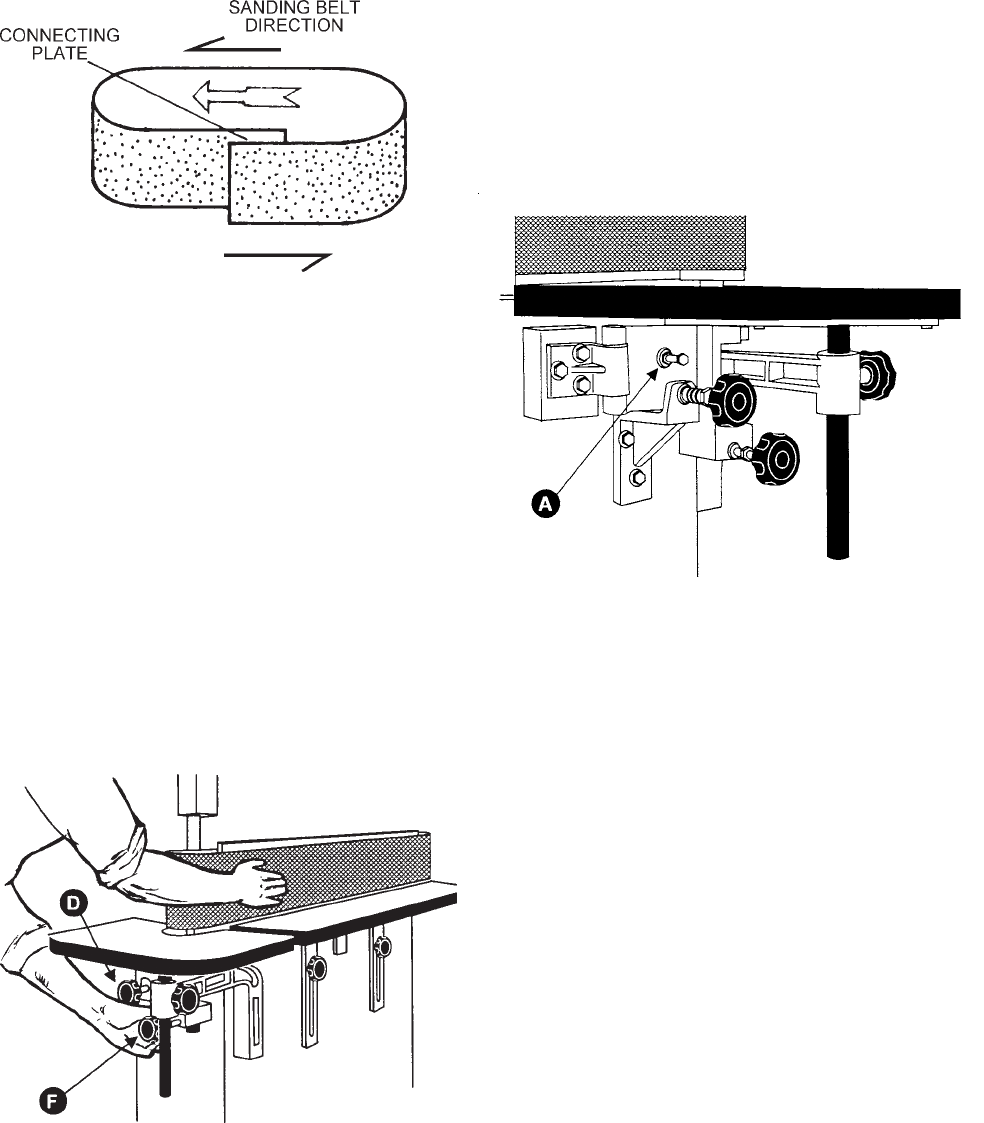
NOTE: Identify the sanding belt direction before you
install the belt, because the belt's rotational direction
must be the same as the machine. An arrow on the
reverse side of the belt shows the proper direction
and should match the arrow direction on the machine
guard. If the belt has no arrow indicator, find the
joint of the belt (where it is layered) and install it ac-
cording to Figure 3.
FIGURE 3
4. Place the new sanding belt between the con-
tact wheel and idler pulley, then adjust the tension
adjustment knob (D). Counterclockwise will maxi-
mize the tension, clockwise will minimize it.
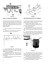
5. Check that the new belt is tracking correctly by
rotating it with one hand, Figure 4, and use your other
hand to make any adjustments to the track adjust-
ment knob (F). To lower the abrasive belt, rotate the
track adjustment knob clockwise. To raise it, rotate
counterclockwise.
NOTE: The track adjustment mechanism is
very sensitive - make these corrections gently.
When properly adjusted, the sanding belt should keep
the same steady level during rotation without mov-
ing too high or too low.
FIGURE 4
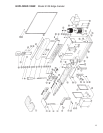
6. Replace safety guard (B), close dust hood and
re-tighten knobs (A).
7. Turn machine on and off quickly several times
to check that the sanding belt rotation is normal and
that it tracks properly. If not, repeat the above pro-
cedure.
SANDING BELT TENSION SPRING
FATIGUE COMPENSATION
Adjustment of the sanding belt will cause spring fa-
tigue when used for a long period. If this happens,
it's not necessary to change the spring. Simply ro-
tate the tension adjustment screw (A), Figure 5, clock-
wise until you achieve the proper tension compen-
sation.
FIGURE 5
FRONT WORK TABLE INCLINATION
Using the inclined table method on this edge sander
may give you better sanding surface contact, de-
creased sanding marks and burr residue, with re-
sults equal to that of an oscillating sanding machine.
To adjust the front work table:
1. Loosen the two fixed knobs (A), Figure 6.
2. Raise the front work table (B) by rotating the
adjustment knob (C) and incline it to the degree de-
sired.
3. Re-tighten the fixed knobs (A).