


7
Unpacking
Open shipping container and check for shipping
damage. Report any damage immediately to your
distributor and shipping agent. Do not discard any
shipping material until the Disc Sander is installed
and running properly. Read the instruction manual
thoroughly for assembly, maintenance and safety
instructions.
Contents of shipping container:
1 DS20 Disc Sander
1 20” Abrasive Paper
1 Brake Assembly
1 Instruction and Parts Manual
1 Warranty Card
Installation
Tools required for assembly:
6mm hex key (“Allen wrench”)
Exposed metal areas of the Disc Sander have
been factory coated with a protectant. This should
be removed with a soft cloth dampened with a
cleaner/degreaser, or kerosene. Do not use
gasoline, acetone or lacquer thinner for this
purpose. Do not get solvents near plastic or rubber
parts, and do not use an abrasive pad because it
may scratch metal surfaces.
1. Remove the bolts holding the Disc Sander to
the pallet, and use an assistant or a hoist to
slide the machine off the pallet.
2. Install the machine in a level, well-lighted
location. Secure it to the floor with good quality
anchor bolts (not provided).
3. Leave enough space around the work area for
loading and off-loading stock and general
maintenance.
Attaching Sanding Paper
NOTE: It is recommended that you first inspect
certain measurements at the disc/table area and
make any needed adjustments (e.g., squaring the
table, disc adjustment, miter gauge adjustment).
This is easier to do against the bare surface of the
disc, before the sanding paper is attached. See the
appropriate sections below.
1. Make sure the surface of the disc is clean and
free of grease or debris.
2. Lower the table all the way and push back the
guard (refer to Figure 6).
3. Remove the backing from the sanding paper to
expose the adhesive, and carefully apply the
sanding paper to the disc on the machine.
Press firmly, starting from the center and
working outward, to remove any air bubbles.
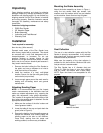
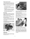
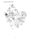
Mounting the Brake Assembly
Attach the brake assembly as shown in Figure 1,
using the two socket head cap screws, lock
washers, and flat washers which are pre-installed
on the machine. Use a 6mm hex key to tighten.
Figure 1
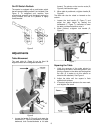
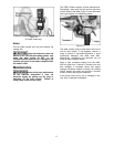
Dust Collection
The use of a dust collection system with the Disc
Sander is strongly recommended. It will maintain
shop cleanliness, and help prevent possible health
hazards caused by wood dust.
Make sure the capacity of the dust collector is
suitable for this size machine. Minimum 600 cubic
feet per minute is recommended.
The Disc Sander has a 4” diameter dust port
(Figure 2). Slide the hose of your dust collector
over the outlet, and secure with a hose clamp.
NOTE: Dryer vent hose is not acceptable for this
purpose.
Figure 2
hose not included