


8
Grounding Instructions
Electrical connections must be
made by a qualified electrician in compliance
with all relevant codes. This machine must be
properly grounded to help prevent electrical
shock and possible fatal injury.
This machine must be grounded. In the event of a
malfunction or breakdown, grounding provides a
path of least resistance for electric current, to
reduce the risk of electric shock to the operator.
Improper connection of the equipment-grounding
conductor can result in a risk of electric shock. The
conductor, with insulation having an outer surface
that is green with or without yellow stripes, is the
equipment-grounding conductor. If repair or
replacement of the electric cord or plug is
necessary, do not connect the equipment-
grounding conductor to a live terminal.
Single Phase Connections
The single phase Sander is factory wired for 230
volts only. It is not supplied with a plug. You may
either install a UL/CSA-listed plug suitable for 230
volt operation, or “hard-wire” the Sander directly to
a service panel (make sure a disconnect is
available for the operator).
It is recommended that the single phase Sander be
connected to a grounded and dedicated, minimum
30 amp circuit with a 30 amp circuit breaker or time
delay fuse. Local codes take precedence over
recommendations.
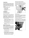
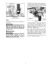
Disc Rotation (Single Phase Only)
The single phase model can be wired to allow disc
rotation in either direction. If you wish to change
disc direction, refer to the diagram inside the motor
junction box. This diagram is repeated in Figure 3.
Figure 3
(Single Phase model disc reversal)
Three Phase Connections
The three phase Sander is factory wired for 230
volts. It is not supplied with a plug. You may either
install a UL/CSA-listed plug suitable for 230 volt
operation, or “hard-wire” the Band Saw directly to a
service panel (make sure a disconnect is available
to the operator).
The three phase Band Saw may be converted to
460 volt operation. Re-connect the motor leads
according to the diagram inside the motor junction
box. (Similar diagrams may be found at the back of
this manual; however, diagrams on the machine
itself should take precedence.)
It is recommended that the three phase 230V
Sander be connected to a grounded and
dedicated, minimum 20 amp circuit with a 20 amp
circuit breaker or time delay fuse. It is
recommended that the three phase 460V sander
be connected to a grounded and dedicated,
minimum 15 amp circuit with a 15 amp circuit
breaker or time delay fuse. Local codes take
precedence over recommendations.
If the Sander is to be hard-wired, make sure the
fuses have been removed or the breakers have
been tripped in the circuit to which the Sander will
be connected. Place a warning placard on the fuse
holder or circuit breaker to prevent it being turned
on while the machine is being wired.
Make sure the voltage of your power supply
matches the specifications on the motor plate of
the Disc Sander.
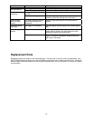
Extension Cords
If an extension cord is necessary make sure the
cord rating is suitable for the amperage listed on
the machine's motor plate. An undersized cord will
cause a drop in line voltage resulting in loss of
power and overheating.
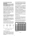
The chart in Figure 4 shows the correct size cord to
use based on cord length and motor plate amp
rating. If in doubt, use the next heavier gauge. The
smaller the gauge number the heavier the cord.
Recommended Gauges (AWG) of Extension Cords
Amps
Extension Cord Length *
25
feet
50
feet
75
feet
100
feet
150
feet
200
feet
< 5 16 16 16 14 12 12
5 to 8 16 16 14 12 10 NR
8 to 12 14 14 12 10 NR NR
12 to 15 12 12 10 10 NR NR
15 to 20 10 10 10 NR NR NR
21 to 30 10 NR NR NR NR NR
*based on limiting the line voltage drop to 5V at 150% of the
rated amperes.
NR: Not Recommended.
Figure 4