


10
Installing Guide Bar
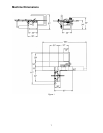
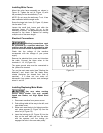
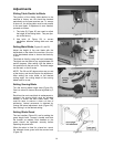
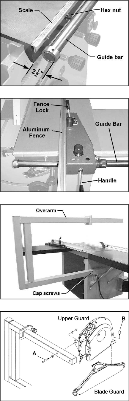
1. Mount the scale (Figure 9) to the edge of
the cast iron table with three M8 x 30 socket
head screws, M8 flat washers, and spacers.
2. Mount the cylindrical steel guide bar to the
edge of the cast iron table, using the four
M12 hex nuts and flat washers.
3. The outside edge of the bar along its entire
length should be approximately 2-1/2" from
the table, to allow for smooth movement of
the fence.
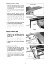
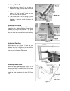
Installing Rip Fence
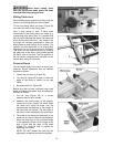
The rip fence assembly (Figure 10) has a cast
iron body with a sliding aluminum fence. Mount
the body by sliding it onto the end of the guide
bar while lifting the handle. Loosen the fence
lock and slide the aluminum fence onto the body
as shown.
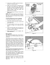
Installing Over Arm
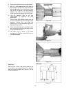
Mount the over arm (Figure 11) with the four
M10 x 30 socket head cap screws, four M10 flat
washers and four M10 hex nuts to the holes on
the side of the frame. Tighten the screws and
nuts securely to the side of the frame.
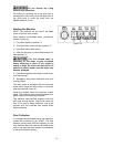
Installing Blade Guard
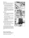
Mount the upper guard assembly (Figure 12) to
the over arm with two M10x80 socket head cap
screws, two M10 flat washers, and an M10 hex
nut (A, Figure 12).
Install the blade guard using the bolt (B, Figure
12).
Figure 9
Figure 10
Figure 11
Figure 12