


9
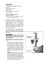
Assembly
Tools needed for assembly (not provided):
Electric drill
center punch and hammer
10.5mm drill bit
M12 x P1.75 tap
12mm, 14mm and 19mm wrenches
5mm hex wrench
Hardware needed for assembly:
4 M12 spring washers
4 M12 x P1.75 hex cap screws (length will
depend upon thickness of table)
Exposed metal areas of the stock feeder have
been factory coated with a protectant. This
should be removed with a soft cloth and a
cleaner/degreaser. Do not use gasoline,
acetone, lacquer thinner or other highly
flammable substances for this purpose. Avoid
getting solvents near plastic or rubber parts, and
do not use an abrasive pad because it may
scratch metal surfaces.
The stock feeder should be mounted securely to
an auxiliary machine in a well-lighted area.
Leave enough space around the work area for
loading and off-loading stock and general
maintenance.
The stock feeder and the
auxiliary machine to which you are mounting
it should both be disconnected from power
during installation.
Refer to pages 14 through 16 for help in placing
the stock feeder on a shaper, table saw or
jointer.
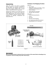
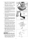
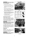
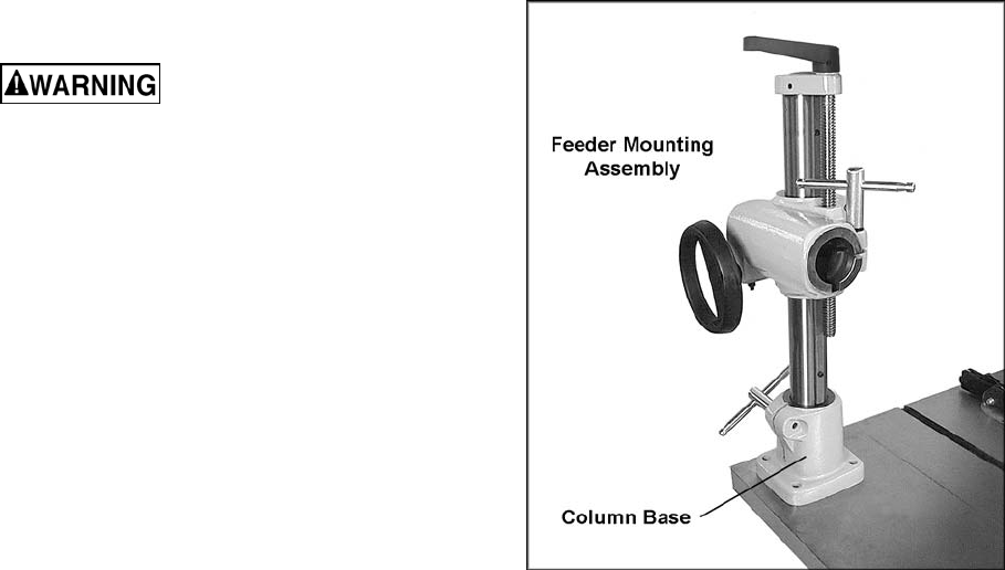
1. Rest the feeder mounting assembly on the
table of the auxiliary machine to determine
the mounting location. (Figure 3 shows it
being mounted to a table saw). Keep in
mind the length of the over arm, so that after
it is connected to the feeder mounting
assembly it will have enough adjustment for
positioning the stock feeder where needed.
Mark the table if needed to identify the
position.
IMPORTANT: Locate the feeder mounting
assembly so that you will not drill through
ribs or supports beneath the table surface.
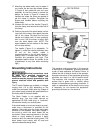
2. Remove the feeder mounting assembly from
the table. Find the boring template that was
provided with your stock feeder, and identify
the centerline spacing for the holes in the
column base for your particular model.
Figure 3