


13
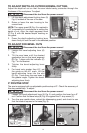
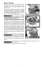
3. To adjust, loosen the bevel-adjustment knob (A) Fig. 8. While keeping
the bevel stop (B) Fig. 8 in contact with the stop screw (C) Fig. 8, use a
screwdriver to turn the adjusting screw (A) Fig. 10 until the blade is square.
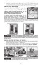
LINE-OF-CUT INDICATOR
Line-of-cut indicator slots (A) Fig. 11 are provided
at the front of the saw base. The right slot is used
to follow a line when making a 0° cut. The left slot
is used to follow a line when making a 45° cut. The
straight side of the notch indicates the cut line.
USING THE EXHAUST NOZZLE
The exhaust nozzle in the closed position (Fig. 12)
directs the sawdust to the rear of the saw. The
exhaust nozzle pointing forward (Fig. 13) directs the
sawdust to the front. To change the position of the
nozzle, push down and turn the nozzle to the new position. An accessory vacuum
hose assembly is available for connecting the exhaust nozzle in the forward
position directly to a shop-type vacuum cleaner.
DO NOT direct sawdust toward yourself or others. To avoid
injury from flying sawdust, keep the exhaust nozzle either in the
forward position or in the closed position. DO NOT insert foreign objects into the
exhaust opening.
INSTALLING THE OPTIONAL RIP GUIDE
1. Insert the rip guide (A) Fig. 14 through the slots (B). Slide the guide in until it
extends through the both slots in the sawbase.
2. Place the compression spring on the thumb screw (C) Fig. 14 (supplied with
the rip guide), and thread into the hole in the saw base. DO NOT TIGHTEN.
3. Adjust the rip guide for the desired width of cut and tighten the thumb screw.
To avoid personal injury and damage to workpiece, extend the
rip guide through both slots in the base.
A
Fig. 11
Fig. 12 Fig. 13
Fig. 14 Fig. 15 Fig. 16
A
B
C