


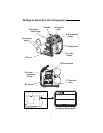
Getting to Know Your Air
Compressor (Continued)
12
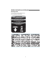
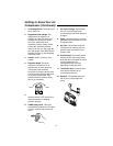
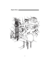
1. Air Storage Tanks. The tanks store
air for later use.
2. Regulated Outlet Gauge. This
gauge shows at-a-glance, air
pressure at outlet. Air pressure is
measured in pounds per square
inch (PSI). Most tools have
maximum pressure ratings. Never
exceed the maximum pressure
rating of the tool you are using. Be
sure this gauge reads ZERO before
changing air tools or disconnecting
hose from outlet.
3. Handle. Used to move the com
pressor.
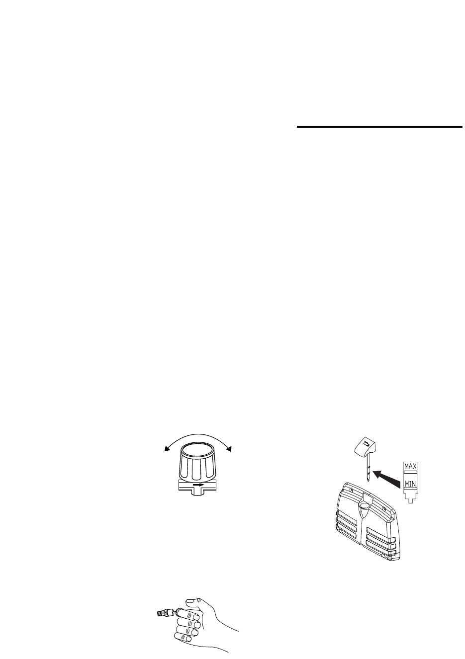
4. Regulator Knob. This knob
controls air pressure to an air
operated tool or paint spray gun.
Turning the knob clockwise
increases air pressure at the outlet.
Turning counterclockwise will lower
air pressure at the outlet. Fully
counterclockwise will shut off the
flow of air completely.
5. Tank Pressure Gauge. Gauge
shows pressure in air receiver indi
cating compressor is building
pressure properly.
6. ASME Safety Valve. This valve
automatically releases air if the tank
pressure exceeds the preset maxi
mum.
7. Air Outlet Fittings. These fittings
are 1/4” universal-style quick
connect fittings and allow rapid tool
changes.
8. Pump. The pump takes in air and
generates the pressurized air in the
air storage tanks.
9. Air Filter. The air filter keeps dirt
and debris from entering the com
pressor pump and reduces com
pressor noise.
10. On/Off Switch. This switch allows
manual control of the compressor.
Note that when the switch is turned
on, the compressor will
automatically start and stop
depending on tank pressure.
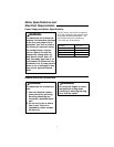
11. Tank Drain Valve. The tank drain
valve allows moisture to be
removed from the tank.
12. Dipstick. The dipstick measures
the oil level in the compressor
pump.
Close
Open