


10
11
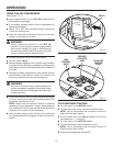
FEATURES
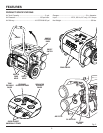
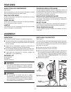
KNOW YOUR AIR COMPRESSOR
See Figure 2.
Before attempting to use this product, familiarize yourself
with all operating features and safety rules.
BUILT-IN CORD WRAP
A built-in cord wrap is provided for convenience in moving
and storing the unit.
DRAIN VALVES
A drain valve is located on each tank for draining condensa-
tion to help prevent tank corrosion.
HANDLE
The handle of your air compressor lifts up for use and folds
down for storage or transportation.
PRESSURE REGULATOR KNOB
Use the pressure regulator knob to adjust the amount of
air being delivered through the hose. Pressing down on the
knob will lock it into place. This prevents movement of the
knob caused by vibration during use.
REGULATOR PRESSURE GAUGE
The current line pressure is displayed on the regulator pres-
sure gauge. This pressure can be adjusted by rotating the
pressure regulator knob.
SAFETY VALVE
The safety valve is designed to automatically release air if
the air receiver pressure exceeds the preset maximum.
TANK PRESSURE GAUGE
The tank pressure gauge indicates the pressure of the air
in the tank.
UNPACKING
This product has been shipped completely assembled.
n Carefully remove the air compressor and any accessories
from the box. Make sure that all items listed in the packing
list are included.
n Inspect the air compressor carefully to make sure no
breakage or damage occurred during shipping.
n Do not discard the packing material until you have care-
fully inspected and satisfactorily operated the product.
n If any parts are damaged or missing, please call
1-866-539-1710 for assistance.
PACKING LIST
Air Compressor
Oil Dipstick
Operator’s Manual
WARNING:
If any parts are damaged or missing do not operate
this tool until the damaged or missing parts are
replaced. Failure to do so could result in possible
serious personal injury.
WARNING:
Do not attempt to modify this tool or create
accessories not recommended for use with this
tool. Any such alteration or modification is misuse
and could result in a hazardous condition leading
to possible serious personal injury.
ASSEMBLY
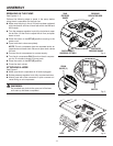
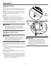
Fig. 3
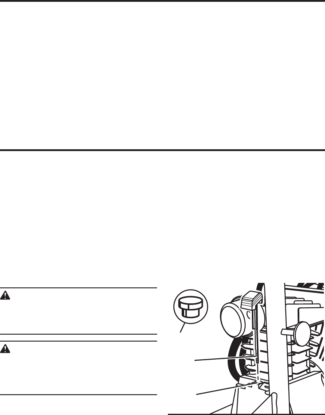
INSTALLING THE DIPSTICK
See Figure 3.
To prevent oil from spilling during shipping, the air compres-
sor has a plug installed in the oil fill hole. Before using the
unit the first time, replace the plug with the oil fill dipstick
and check the oil level.
n Remove the plug from the oil fill hole.
n Insert the dipstick into the oil fill hole.
n Remove the dipstick and check the oil level, making sure
the oil registers between the MIN and MAX reference lev-
els on the dipstick. If the level does not register between
those areas, refer to Checking the Oil in the Operation
section of this manual.
n Replace the dipstick.
OIL FILL
HOLE
OIL PLUG
DIPSTICK