Ridge Tool Company
7
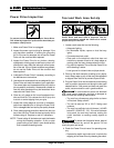
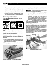
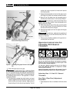
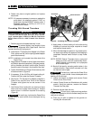
Figure 5 – Threading 2” Pipe With Power Drive
Positioned On Right Side Of Vise
Figure 6 – Threading Using Pipe Wrench As A Support
Arm
5. Place Die Head over end of pipe.
To avoid serious injury, make sure Power
Drive is correctly positioned on support arm (Figures 4, 5
& 6). For right hand threads, Die Head will rotate clockwise
(looking at the face of the Die Head). Forces developed by
the threading torque will be in the opposite or counter-
clockwise direction.
6. Simultaneously actuate the switch button and exert
pressure against the Die Head with the palm of free
hand to make sure thread is started. Apply plenty of
thread cutting oil to the dies during threading. This will
reduce the torque required to thread and improve
the thread quality.
7. Keep switch depressed until end of the pipe is even
with edge of the dies and release the switch button.
8. Back off the Die Head from the threaded pipe by
actuating the switch button in the reverse direction.
To avoid injury, hold onto the Power Drive
handle firmly to resist handle forces developed while
backing off the Die Head.
9. When dies clear the end of the pipe, grip the handle
on top of the Power Drive and remove the Power
Drive and Die Head from the pipe.
10. Remove the support arm from the pipe and the pipe
from the vise.
To avoid injury, make sure long sections of
pipe are supported at the end farthest away from the
vise prior to removal.
11. Clean up any oil spills or splatter on the ground sur-
rounding the vise and oiler.
Operation Instructions For
Threading With Geared
Threaders
WARNING
Do not wear gloves or loose clothing when oper-
ating Power Drive. Keep sleeves and jackets but-
toned. Do not reach across the geared threader.
Do not use this Power Drive if the switch is broken.
Always wear eye protection to protect eyes from
dirt and other foreign objects.
To prevent tipping, proper set-up of the Power
Drive and Geared Threader is required. Follow
instructions carefully.
Geared Threaders weigh 95 to 160 pounds. Two (2)
persons should be used to lift these threaders.
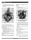
Adjusting Nos. 141 And 161 Geared
Threaders
Cam Plate (Pipe Size) Adjustment
Procedure
1. Place threader on floor or workbench with drive shaft
up.
No. 700 Portable Power Drive
No. 418 Oiler
Pipe
No. 775 Support Arm
Switch Button
WARNING
WARNING
WARNING


