


15
ASSEMBLY
UNPACKING
This product requires assembly.
Carefully lift the saw from the carton and place it on a level
work surface.
WARNING:
Do not use this product if any parts on the Loose
Parts List are already assembled to your product
when you unpack it. Parts on this list are not as-
sembled to the product by the manufacturer and
require customer installation. Use of a product that
may have been improperly assembled could result
in serious personal injury.
Inspect the tool carefully to make sure no breakage or
damage occurred during shipping.
Do not discard the packing material until you have carefully
inspected and satisfactorily operated the tool.
The saw is factory set for accurate cutting. After
assembling it, check for accuracy. If shipping has influ-
enced the settings, refer to specific procedures explained
in this manual.
If any parts are damaged or missing, please call
1-866-539-1710 for assistance.
WARNING:
If any parts are damaged or missing do not oper-
ate this tool until the parts are replaced. Use of
this product with damaged or missing parts could
result in serious personal injury.
WARNING:
Do not attempt to modify this tool or create
accessories not recommended for use with this
tool. Any such alteration or modification is misuse
and could result in a hazardous condition leading
to possible serious personal injury.
WARNING:
Do not connect to power supply until assembly is
complete. Failure to comply could result in acci-
dental starting and possible serious personal injury.
WARNING:
Never stand directly in line with the blade or allow
hands to come closer than 3 in. to the blade. Do
not reach over or across the blade. Failure to heed
this warning can result in serious personal injury.
WARNING:
To avoid serious personal injury, always make sure
the table saw is securely mounted to a workbench
or an approved leg stand. NEVER operate the saw
on the floor.
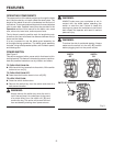
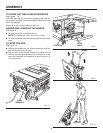
MOUNTING HOLES
The table saw must be mounted to a firm supporting, waist
high surface such as a workbench or leg stand. Four bolt
holes have been provided in the saw’s base for this purpose.
Each of the four mounting holes should be bolted securely
using 1/4 in. machine bolts, lock washers, and hex nuts (not
included). Bolts should be of sufficient length to accommodate
the saw base, lock washers, hex nuts, and the thickness of
the workbench. Tighten all four bolts securely.
Carefully check the workbench after mounting to make sure
that no movement can occur during use. If any tipping, slid-
ing, or walking is noted, secure the workbench to the floor
before operating.
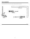
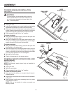
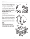
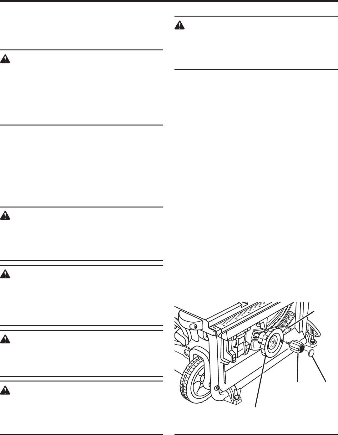
TO INSTALL THE HANDLE ASSEMBLY
See Figure 6.
Lift the end cap off the handle assembly using a flat blade
screwdriver.
Hold the nylok nut securely and turn the screw counter-
clockwise to remove the nut completely.
NOTE: Do not remove the screw from the handle or the
washer from the end of the screw.
Place the nylok nut into the recessed hole on the back of
the height/bevel adjusting handwheel and hold in place.
Slide the handle, screw, and washer into the hole on the
height/bevel adjusting handwheel.
Using a flathead screwdriver, turn the screw clockwise and
tighten in place.
Push the end cap back in place on the end of the handle.
NuT
HEIgHT/BEvEL
aDJuSTINg
HaNDWHEEL
HaNDLE
aSSEMBLY
Fig. 6
END
CaP