


Page 9
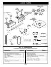
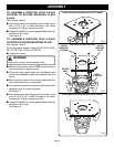
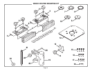
Fig. 6
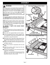
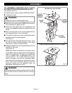
Fig. 7
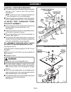
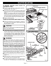
Fig. 8
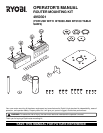
ASSEMBLY
TO ASSEMBLE ROUTERS WITH 2-HOLE
PATTERN TO ROUTER MOUNTING PLATE
(cont'd):
See Figures 5 and 6.
■ Secure the router mounting plate to the router using
two 5/16-18 x 3/4 in. bolts provided in the router
mounting kit. Tighten screws securely.
■ Properly installed, the mounting plate will be securely
attached to the router.
See Figure 6
.
TO ASSEMBLE ROUTERS WITH 3-HOLE
PATTERN TO ROUTER MOUNTING PLATE:
See Figures 7 and 8.
For Ryobi routers, model numbers R160, R161, R165,
RE170, RE170VS, R180, and RE185.
■ Unplug the router.
WARNING:
Unplug the router to avoid possible injury.
■ Make sure the router switch is OFF and the router is
not connected to a power source.
■ Place the router upside down on a workbench and
remove the subbase screws and subbase from the
router.
■ Align mounting holes of the mounting plate with the
three threaded holes in router base.
■ The switch handle of the router should be facing the
squared end of the mounting plate.
See Figure 7.
■ Secure the router mounting plate to the router using
three 5/16-18 x 3/4 in. bolts provided in the router
mounting kit. Tighten screws securely.
■ Properly installed, the mounting plate will be securely
attached to the router.
See Figure 8.
ROUTER
MOUNTING
SCREWS
FRONT
OF ROUTER
ROUTER
MOUNTING
PLATE
ROUTER WITH 3–HOLE PATTERN
3–HOLE ROUTER WITH MOUNTING PLATE ATTACHED
2–HOLE ROUTER WITH MOUNTING PLATE ATTACHED
ROUTER
BASE