


6 7
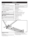
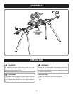
ASSEMBLING AND INSTALLING MATERIAL
WORK SUPPORTS
See Figures 3 - 5.
The material work supports help balance the workpiece
during cutting operations.
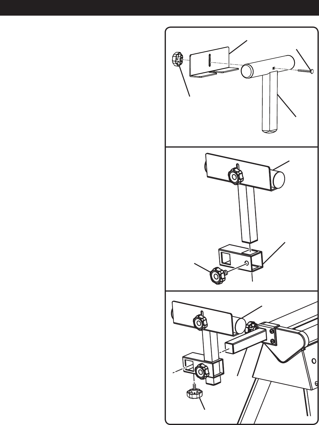
To assemble the work support:
n Slide a carriage bolt (M6 x 60 mm) through the square
hole in the work support and extend through the other
side.
n Place the work stop over the end of the bolt
n Thread a work stop adjustment knob over the end of the
bolt and tighten to secure.
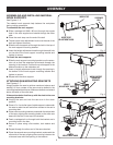
n Slide the work support rail through the hole in the top of
the work support mounting bracket.
n Insert the height adjustment knob through the small hole
on the side of the work support mounting bracket and
tighten to secure.
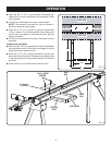
To install the work supports:
n Slide the work support mounting bracket over the exten-
sion rail so that the extension rail extends through the
opening in the bracket. Position the work support at the
desired location on the extension rail.
n Insert a length adjustment knob through the opening in
the bottom of the work support mounting bracket and
tighten to secure.
n Repeat with the other support.
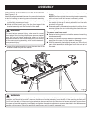
ATTACHING SAW MOUNTING BRACKETS
See Figures 6 - 7.
Always position the saw to achieve maximum balance and
stability. All four corners of the saw must be bolted to the
mounting brackets before use. Make sure bolts do not extend
above the table of the miter saw.
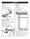
If the saw has holes that line up with the slots in the saw
mounting brackets:
n Unplug the saw and lock the saw arm in the down
position.
n Place a 2 x 4 or similar type of stable support underneath
the saw to raise the saw and allow access to the saw’s
mounting feet.
n Place a saw mounting bracket underneath the raised side
of the saw, aligning the mounting holes on the miter saw
base with the slot in the top of the bracket.
n Feed a carriage bolt up through both the bracket and a
mounting hole in the saw.
n Secure in place using a flat washer, lock washer and
nut.
n Repeat through the other end of the same bracket.
n Place the second saw mounting bracket underneath the
other side of the saw, aligning the mounting holes on the
miter saw base with the opening in the bracket.
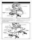
ASSEMBLY
Fig. 4
WORK
SUPPORT
WORK SUPPORT
MOUNTING
BRACKET
HEIGHT
ADJUSTMENT KNOB
Fig. 5
WORK
SUPPORT
EXTENSION
RAIL
LENGTH
ADJUSTMENT KNOB
Fig. 3
CARRIAGE
BOLT
WORK STOP
ADJUSTMENT KNOB
WORK
SUPPORT
WORK STOP