


9
4 x3
6
4 x36
4 x36
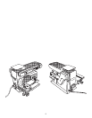
Fig. 4
Fig. 6
ASSEMBLY
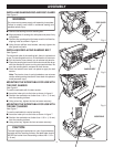
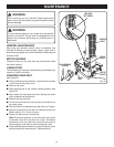
INSTALLING SANDING DISC AND DISC GUARD
See Figure 4.
WARNING:
Do not connect to power supply until assembly is complete.
Failure to comply could result in accidental starting and
possible serious injury.
■ Remove the backing from the sanding disc.
■ Align perimeter of sanding disc with plate and press firmly
into position.
■ Position disc guard against the lower one-third of the disc,
aligning holes as shown in figure 4.
■ Using the two phillips head screws, securely tighten the
disc guard into place.
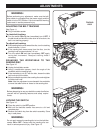
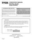
INSTALLING/REPLACING SANDING BELT
See Figure 5.
On the smooth side of the sanding belt, there is a directional
arrow. The sanding belt must run in the direction of the arrow.
■ Pull the tension lever toward you to release belt tension.
■ Place the sanding belt over the drive drum and idler drum
with the directional arrows running counterclockwise. Be
sure the sanding belt is centered on both drums.
■ Push the tension lever back into place to apply the belt
tension.
Note: The tension lever is spring loaded so use extreme
caution when pushing the tension lever back into place to
avoid personal injury.
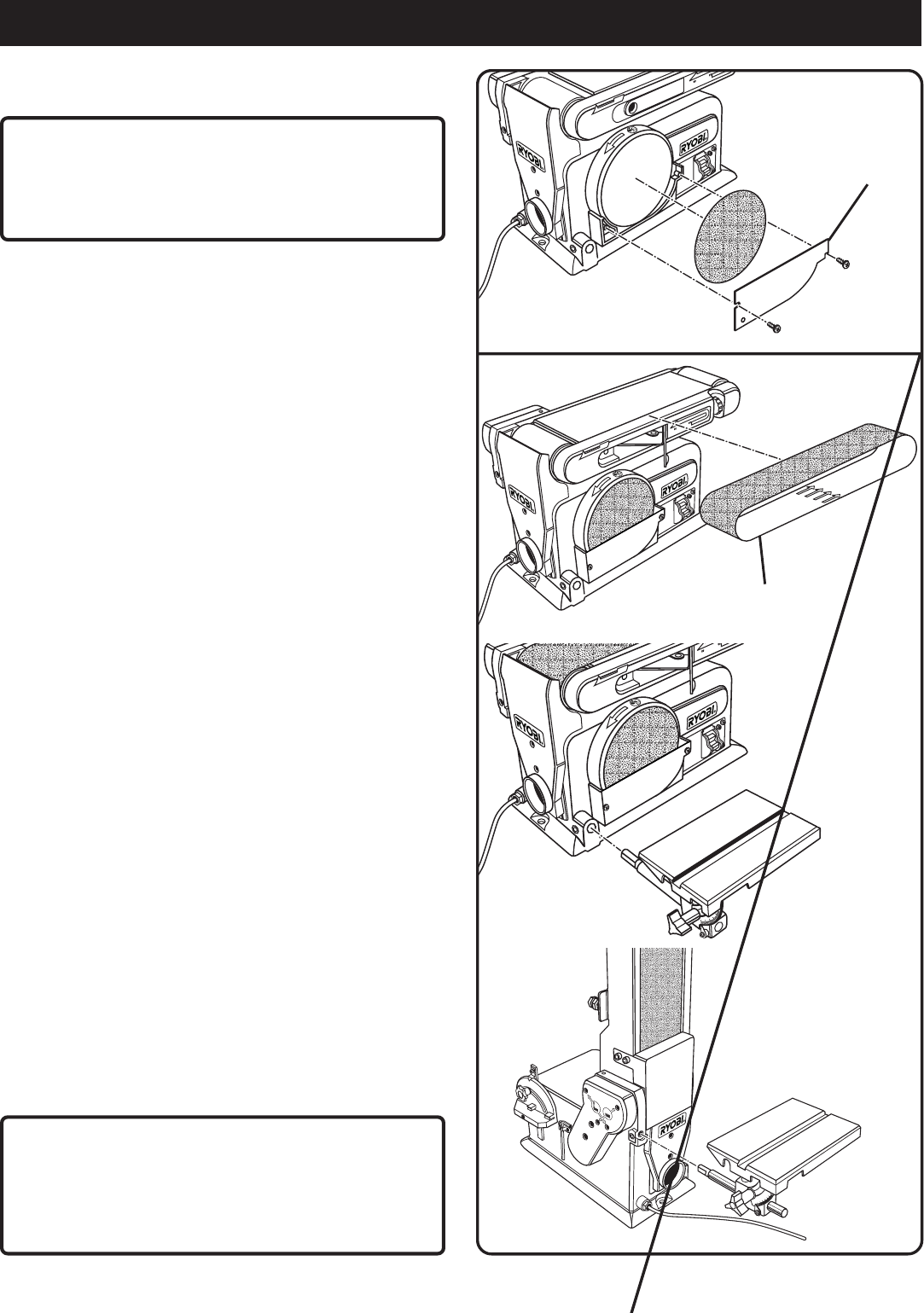
MOUNTING THE WORKTABLE FOR USE WITH
THE DISC SANDER
See Figure 6.
To use the worktable with the disc sander:
■ Insert the index pin into the hole as shown in figure 6.
■ Position the worktable not further than 1/16 in. (1.6 mm)
from the sanding surface.
■ Using a hex key, tighten the hex set screw securely.
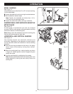
MOUNTING THE WORKTABLE FOR USE WITH
THE BELT SANDER
See Figure 7.
To use the worktable for vertical sanding:
■ Insert the index pin into the hole as shown in figure 7.
■ Position the worktable not further than 1/16 in. (1.6 mm)
from the sanding surface.
■ Using a hex key, tighten the hex set screw securely.
CAUTION:
To avoid trapping the workpiece or your fingers between
the table and the sanding surface, the table edge should
NEVER be further from the sanding surface than 1/16 in.
(1.6 mm).
DISC GUARD
SANDING BELT
WORKTABLE
Fig. 5
WORKTABLE