


Page 29
MAINTENANCE
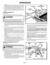
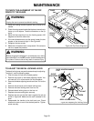
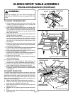
TO ADJUST THE BEVEL LOCKING LEVER
The bevel locking lever may work loose and require adjusting.
To adjust it, use the following steps.
1. Push the lever full left to the locked position.
2. Remove the screw on the blade adjusting handle. You
will need a 3/16 in. allen wrench for this procedure.
3. Remove the blade adjusting handle and cam. Pull out the
cam.
4. Remove the set screw on the bevel locking lever.
5. Remove the bevel locking lever from hex nut.
6. Relocate bevel locking lever on the hex nut.
7. Replace set screw and tighten securely.
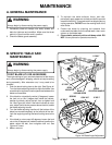
8. Replace the cam so that the lobe is against the tab as
shown in Figure 46. Make sure the cam is seated in the
lever.
9. Reassemble the handle to the shaft and cam. Check
whether the lever is now in the desired position. Tighten
screw securely.
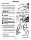
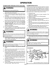
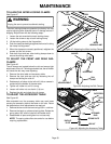
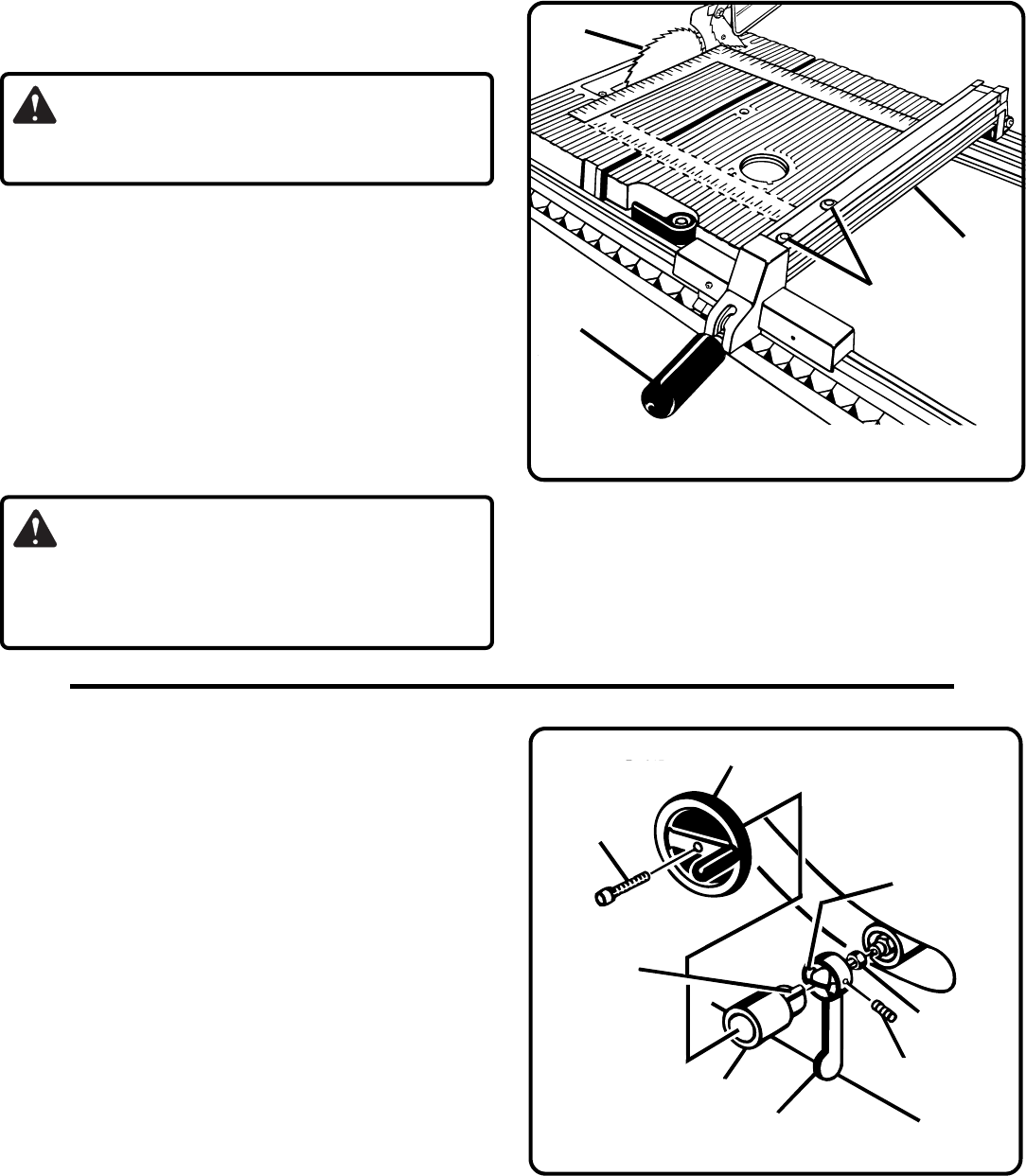
Figure 45: Rip Fence Alignment
BLADE
SCREWS
RIP
FENCE
LOCKING
HANDLE
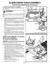
TO CHECK THE ALIGNMENT OF THE RIP
FENCE TO THE BLADE
WARNING:
Unplug the saw to prevent accidental starting.
1. Raise the locking handle to permit the rip fence to be
moved.
2. Place a framing square beside the blade and move the rip
fence up to the square. Take the dimension on the rip
scale.
3. Move the fence back and turn the framing square 180
degrees to check the other side.
4. If the two dimensions are not the same, loosen the two
screws on the fence and align it.
See Figure 45.
5. Retighten the two screws.
6. Make two or three test cuts on scrap wood. If the cuts are
not true, repeat the process.
WARNING:
Before plugging the saw back in to make test cuts, make
sure the switch is in the OFF position and the blade guard
is in place. Failure to do so may result in serious injury.
Figure 46: Adjusting the Locking Lever
SET SCREW
TAB
BLADE ADJUSTING HANDLE
SOCKET
HEAD SCREW
HEX NUT
CAM
BEVEL LOCKING LEVER
LOBE