


31
OPERATION
MAKING A BEVEL CROSS CUT
See Figures 40 - 41.
It is recommended that you place the piece to be saved on
the left side of the blade and that you make a test cut on
scrap wood.
WARNING:
Make sure the blade guard assembly is installed and
working properly to avoid possible serious injury.
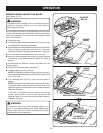
Unlock the bevel locking lever.
Remove the rip fence by lifting the locking handle.
Turn the height/bevel adjusting handwheel until the bevel
indicator is at the desired angle. Push the bevel locking
lever securely to the left to lock the angle.
Set the blade to the correct depth for the workpiece.
Set the miter fence to 90° and tighten the lock knob.
Place a support (the same height as saw table) behind
the saw for the cut work.
Make sure the wood is clear of the blade before turning
on the saw.
Let the saw blade build up to full speed before moving
the miter fence and the workpiece into the blade.
Hold the workpiece firmly with both hands on the miter
fence and feed the workpiece into the blade.
When the cut is made, turn the saw off. Wait for the
blade to come to a complete stop before removing the
workpiece.
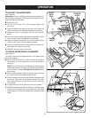
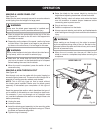
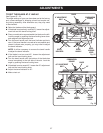
MAKING A BEVEL RIP CUT
See Figure 42.
It is recommended you make test cuts on scrap wood.
WARNING:
Make sure the blade guard assembly is installed and
working properly to avoid serious personal injury.
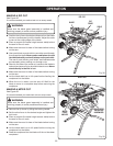
Remove the sliding miter fence.
Adjust the bevel angle to the desired setting.
Set the blade to the correct depth.
Position the rip fence the desired distance from the left
side of the blade and lock down the handle.
If ripping a piece larger than 36 in. long, place a support
the same height as the table surface behind the saw for
the cut work.
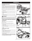
Turn the power switch to the ON position.
Position the workpiece flat on the table with the edge
flush against the rip fence. Let the blade build up to full
speed before feeding the workpiece into the blade.
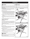
Using a push stick and/or push blocks, slowly feed the
workpiece toward the blade. Stand slightly to the side of
the wood as it contacts the blade to reduce the chance
of injury should kickback occur.
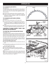
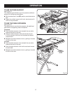
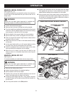
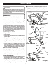
Fig. 40
VIEWED FROM THE FRONT, BELOW THE TABLE SAW
BEVEL
LOCKING LEVER
TO LOOSEN
TO
TIGHTEN
HEIGHT/BEVEL ADJUSTING
HANDWHEEL
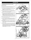
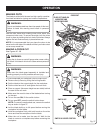
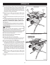
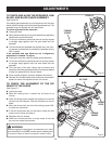
Fig. 41
BEVEL CROSS CUT
BLADE
ANGLED
MITER
FENCE
STRAIGHT
BEVEL LOCKING
LEVER