


36
ADJUSTMENTS
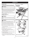
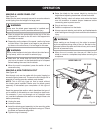
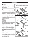
TO CHECK AND ALIGN THE SPREADER, SAW
BLADE, AND BLADE GUARD ASSEMBLY
See Figure 50.
If the blade guard assembly is out of alignment with the saw
blade, adjust the alignment of the blade guard assembly. The
spreader must be aligned with the saw blade.
To check alignment of the spreader:
Unplug the saw.
Raise the saw blade by turning the height/bevel adjusting
handwheel counterclockwise.
Lift the anti-kickback pawls and place a framing square
or straight edge against both the saw blade and the
spreader.
The saw blade and spreader are aligned when the fram-
ing square contacts both the blade and spreader evenly
with no gaps.
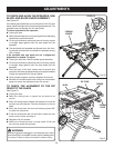
If the spreader and saw blade are not in alignment,
adjustment is needed. To adjust:
Unplug the saw then raise the blade guard assembly.
Lift the anti-kickback pawls and place a framing square
or straight edge against both the saw blade and the
spreader.
From the back of the saw, loosen the two screws and
reposition the blade guard assembly left or right as needed
to align the spreader with the saw blade.
Once properly aligned, securely retighten the screws.
Recheck the marked blade tooth using the combination
square to insure the adjustment has not moved.
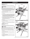
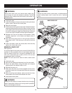
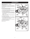
TO CHECK THE ALIGNMENT OF THE RIP
FENCE TO THE BLADE
See Figure 51.
Unplug the saw.
Raise the locking lever to permit the rip fence to be
moved.
Place a framing square beside the blade and move the
rip fence up to the square. Take the dimension on the rip
scale.
Move the fence back and turn the framing square 180°
to check the other side.
If the two dimensions are not the same, loosen the two
screws on the fence and align it.
Retighten the two screws.
Make two or three test cuts on scrap wood. If the cuts
are not true, repeat the process.
WARNING:
Before plugging the saw back in to make test cuts, make
sure the switch is in the OFF position and the blade guard
is in place. Failure to do so can result in serious injury.
BLADE
SCREWS
RIP FENCE
LOCKING
LEVER
FRAMING
SQUARE
SCREW (2)
FRAMING
SQUARE
Fig. 51
Fig. 50