


10
FEATURES
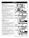
LOCK-ON BUTTON
See Figure 3.
The cut-off machine is equipped with a lock-on
feature which is convenient when continuous cutting for
extended periods of time is required. To engage the lock-on
feature, depress switch trigger, push in and hold the lock-on
button located on the side of the handle, then release switch
trigger. Release lock-on button and machine will continue
running.
To release lock-on feature, depress switch trigger and
release.
If you have the lock-on feature engaged during use and
the machine becomes disconnected from power supply,
disengage the lock-on feature immediately.
TRIGGER LOCK
See Figure 4.
To prevent unauthorized use of the cut-off machine, we
suggest that you disconnect it from the power supply and
lock the switch in the off position. To lock the switch, install
a padlock (not included) through the hole in the switch
trigger. A lock with a shackle up to 1/4 in. diameter may be
used. When the lock is installed and locked, the switch is
inoperable. Store the padlock key in another location.
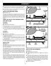
VISE CLAMP
A vise clamp has been provided with the cut-off machine.
It is located on the end of the vise screw and provides
greater control by clamping the material to the fence. It also
prevents the material from creeping toward the wheel during
a cutting operation.
ADJUSTABLE FENCE
The fence on the cut-off machine has been provided to sup-
port the material and provide clamping support to the vise
for holding the material securely when making all cuts. It
is an adjustable fence that has been provided to make the
cut-off machine more versatile. It adjusts from 0° to 45° to
the right for making angled cuts. The hole pattern allows it
to be moved forward when making cuts in tall or thick stock,
such as square stock or tube stock. The hole pattern allows
it to be moved back when making cuts in stock that is thin
or wide, such as angle stock.
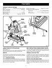
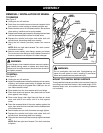
CARRYING HANDLE
For convenience when carrying or transporting the cut-
off machine from one place to another, a carrying handle
has been provided on top of the machine arm as shown in
figure 3. To transport, turn off and unplug the machine, then
lower machine arm and lock it in the down position. Use the
transport chain to lock machine arm in the down position.
Fig. 3
POWER
CORD
UPPER
WHEEL GUARD
LOWER
WHEEL GUARD
CARRYING
HANDLE
MACHINE ARM
FENCE
BOLTS
ADJUSTABLE
FENCE
VISE CLAMP
RUBBER FEET (3)
QUICK LOCK-
RELEASE LEVER
14 in.
ABRASIVE
WHEEL
DEPTH
STOP
VISE CRANK
HANDLE
SWITCH
TRIGGER
LOCK-ON
BUTTON
PADLOCK
TRIGGER
LOCK