


12
REMOVAL / INSTALLATION OF WHEEL
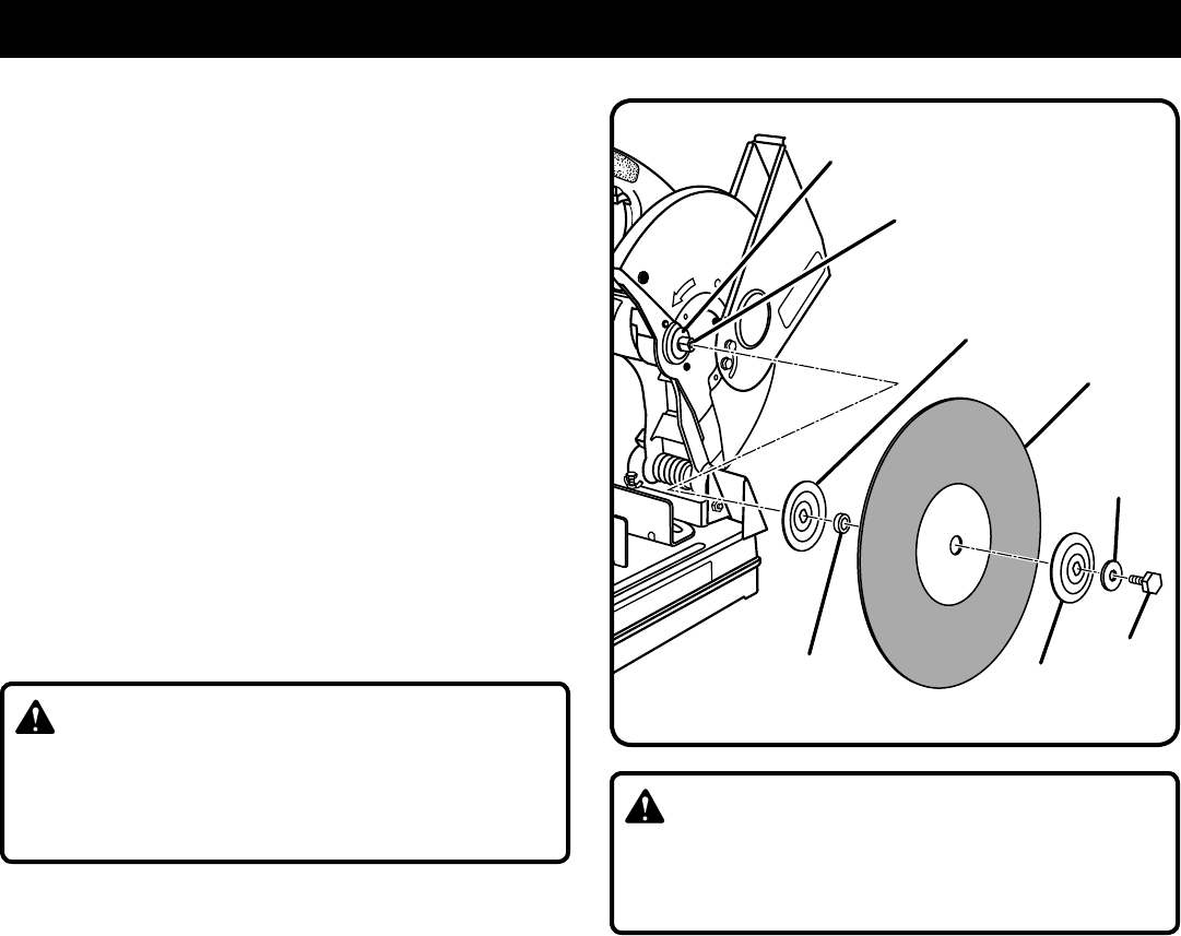
TO REMOVE
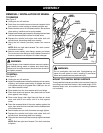
See Figure 5.
n Unplug the cut-off machine.
n Push down on machine arm and remove transport chain
from hook on motor housing to release machine arm.
n Raise machine arm to its full raised position. Be cautious
when raising, machine arm is spring loaded.
n Rotate lower wheel guard upward, exposing the hex head
bolt that secures abrasive wheel to wheel arbor.
�n Depress the spindle lock button and rotate bolt until
spindle locks, preventing shaft from rotating.
n� Using the hex wrench provided, loosen and remove
bolt.
NOTE: Bolt has right hand threads. Turn bolt counter-
clockwise to loosen.
�n Remove outer washer, outer flange, spacer, and wheel.
Do not remove inner flange or inner washer. Removal of
these two parts are not required for wheel changes.
WARNING:
If inner flange or inner washer has been removed, replace
both before placing wheel on spacer and wheel arbor.
Failure to do so could cause an accident since wheel will
not tighten properly.
TO INSTALL
See Figure 5.
n Unplug the cut-off machine.
n Inspect the replacement wheel for defects such as cracks,
chipping, and correct speed rating. If defects are found
or the speed rating is not greater than 3,900 rpm, do not
use. Select another wheel.
�n Clean debris from the inner washer and inner flange.
�n Place new wheel over spacer, then place both on wheel
arbor against inner flange.
�n Clean outer flange, then align flats with flats on wheel
arbor and slide it onto arbor until it is flush against
wheel.
�n Place the recessed side of the outer washer against the
arbor, then insert the hex head bolt into the threaded end
of the wheel arbor.
�n Start threads and turn bolt clockwise to snugly tighten.
�n Depress the spindle lock button and rotate bolt until
spindle locks, preventing shaft from rotating.
�n Using the hex wrench provided, securely tighten hex head
bolt.
NOTE: Bolt has right hand threads. Turn bolt clockwise
to tighten.
WARNING:
Do not overtighten hex head bolt. Overtightening can
cause the new wheel to crack, resulting in premature
failure and possible serious personal injury.
MOUNT TO A METAL WORK SURFACE
�Three predrilled holes are provided in the machine’s base for
mounting to a metal work surface. Use proper length, 3/8 in.
diameter bolts, nuts, and washers for mounting (hardware
not included).
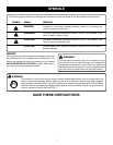
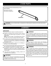
Fig. 5
OUTER
WASHER
OUTER
FLANGE
14 in.
ABRASIVE
WHEEL
SPACER
INNER
FLANGE
HEX HEAD
BOLT
WHEEL
ARBOR
INNER
WASHER
ASSEMBLY