


14
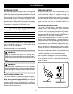
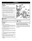
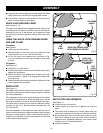
Fig. 9
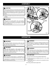
Fig. 10
QUICK LOCK-RELEASE LEVER
WITH THREADS NOT ENGAGED
VISE
CLAMP
VISE CRANK
HANDLE
VISE
SCREW
VISE
CLAMP
VISE
CRANK
HANDLE
QUICK LOCK-
RELEASE LEVER
WITH THREADS
ENGAGED
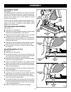
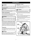
n Using the hex wrench supplied, securely tighten hex head
bolts. Return hex wrench to its storage area in base.
�n This position is good for cutting tall and thick pieces of
stock, such as square or tube stock.
QUICK LOCK-RELEASE LEVER
See Figures 9 - 10.
The quick lock-release lever engages the vise clamp to be
used along with the fence to provide a vise for securing the
workpiece to be cut. It also allows you to open and close
the vise quickly without repetitive turning of the vise crank
handle.
USING THE QUICK LOCK-RELEASE LEVER
AND VISE CLAMP
To loosen:
See Figure 9.
n Unplug the cut-off machine.
�n Release tension on the vise clamp by rotating the vise
crank handle 1/2 to 1 turn counterclockwise.
�n Lift up the quick lock-release lever as shown in fig-
ure 9 and pull back on vise crank handle to slide open
the vise.
To tighten:
See Figure 10.
n Unplug the cut-off machine.
�n Push the vise crank handle forward to slide the vise clamp
against the workpiece.
�n Rotate the quick lock-release lever forward and push
down as shown in figure 10 to engage its threads with
the vise screw.
�n Rotate the vise crank handle clockwise to tighten the vise
clamp against the workpiece.
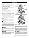
DEPTH STOP
See Figure 11.
The depth stop limits the wheel's downward travel. It allows
the wheel to go below the machine base enough to maintain
full cutting capacities.
The adjustable depth stop is a bolt threaded into the base
at the rear of the machine. To adjust the depth stop, use the
hex wrench supplied to raise or lower the depth stop bolt.
The depth stop is factory set to provide maximum cutting
capacity for the 14 in. abrasive wheel provided with the
cut-off machine.
When the diameter of the wheel has been reduced due to
wear, it may be necessary to adjust the depth stop to provide
maximum cutting capacity. When a new abrasive wheel is
installed, it is necessary to check the clearance of the wheel
to the machine base support.
ASSEMBLY
DEPTH STOP ADJUSTMENTS
See Figure 11.
n Unplug the cut-off machine.
�n Loosen depth stop bolt that is against the machine
base.
�n The depth stop is lowered by turning depth stop bolt
clock-wise and raised by turning bolt counterclockwise.
�n By pressing down on the machine arm, lower the wheel
and check clearance and maximum cutting distance
(distance from adjustable stationary vise where wheel
enters) to front of machine base slot.
�n Adjust if necessary.