


12
13
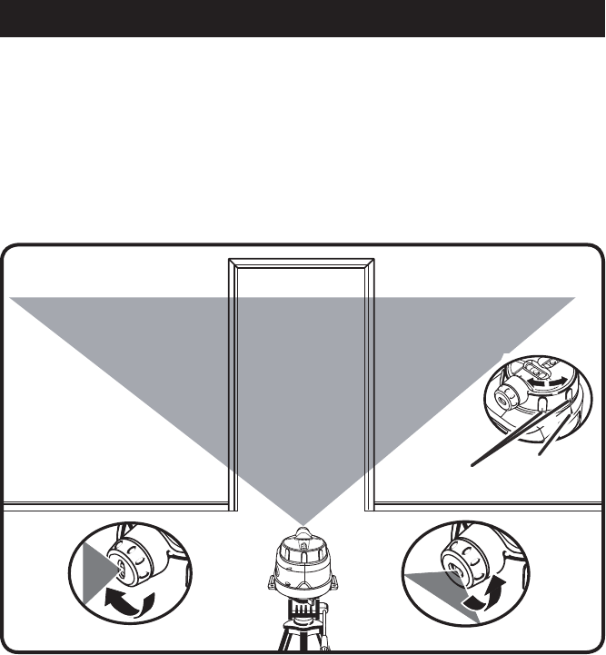
OPERATION
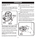
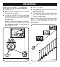
ADJUSTING THE LASER LINE
See Figure 8.
The laser level will project a straight line across
an obstruction or interference, as well as around
inside corners and onto adjacent surfaces. The
line can be adjusted in two ways:
n The line can be rotated 360˚ by turning
the laser head in a clockwise or coun-
terclockwise direction. To move the line
in 45° increments, align one of the raised
Fig. 8
ridge marks on the laser head with one of
the arrow marks on the body of the laser,
then rotate the laser head in the desired
direction until the next ridge is aligned with
the same arrow mark. Relevel the unit for
each wall, adjacent surface, or direction a
line is generated towards.
n The line can also be rotated up to 90°, from
vertical to horizontal, by turning the lens
adjustment ring in a clockwise or counter-
clockwise direction.
HORIZONTAL BEAM
VERTICAL BEAM
ARROW
MARK
RIDGE
MARKS