


19
1
2
45
0
0
15
22
30
45
50
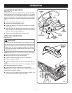
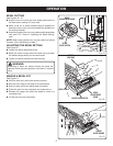
Fig. 23
BEVEL
ADJUSTMENT
KNOB
BLADE
CARPENTER'S
SQUARE
ADJUSTMENT
SCREW
HEX NUT
POSITIVE 0°
BEVEL STOP
ADJUSTMENTS
WARNING:
Before performing any adjustment, make sure the bat-
tery pack is removed from tool and the switch is in the
OFF position. Failure to heed this warning could result in
serious personal injury.
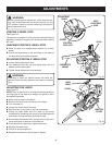
POSITIVE 0° BEVEL STOP
See Figure 23.
The saw has a positive 0° bevel stop that has been factory
adjusted to assure 0° angle of the saw blade when making
90° cuts.
CHECKING POSITIVE 0° BEVEL STOP
Place the saw in an upside down position on a work-
bench.
Check the squareness of the saw blade to the base of
the saw using a carpenter’s square.
ADJUSTING POSITIVE 0° BEVEL STOP
Loosen bevel adjustment knob.
Turn setscrew with hex key and adjust base until it is
square with the saw blade.
Tighten bevel adjustment knob securely.
WARNING:
Attempting a bevel cut without having the bevel ad-
justment knob securely tightened can result in serious
injury.
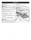
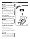
ADJUSTING THE LASER
See Figure 24.
NOTE: Draw a pencil line on a scrap workpiece parallel to
the long edge of the base as a straight line guide to aid in
the adjusting process.
Make sure the laser is turned off.
Remove the laser cover by lifting it off its base.
Turn the laser on.
Loosen the screw inside the laser.
Rest the front of the base on a scrap workpiece.
Adjust the laser beam with the mark on the scrap
workpiece by loosening the screw to the laser aperture
and slowly moving the laser guide left or right.
Since blade thicknesses vary, always make a trial cut in
scrap workpiece to ensure an accurate cut.
Once alignment is achieved, tighten the screw.
Replace the laser cover.
Check for proper alignment.
Repeat as necessary until the laser is aligned.
LASER
COVER
SCREW
Fig. 24
PENCIL
LINE
LONG EDGE
OF BASE