


Page 7
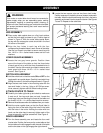
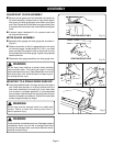
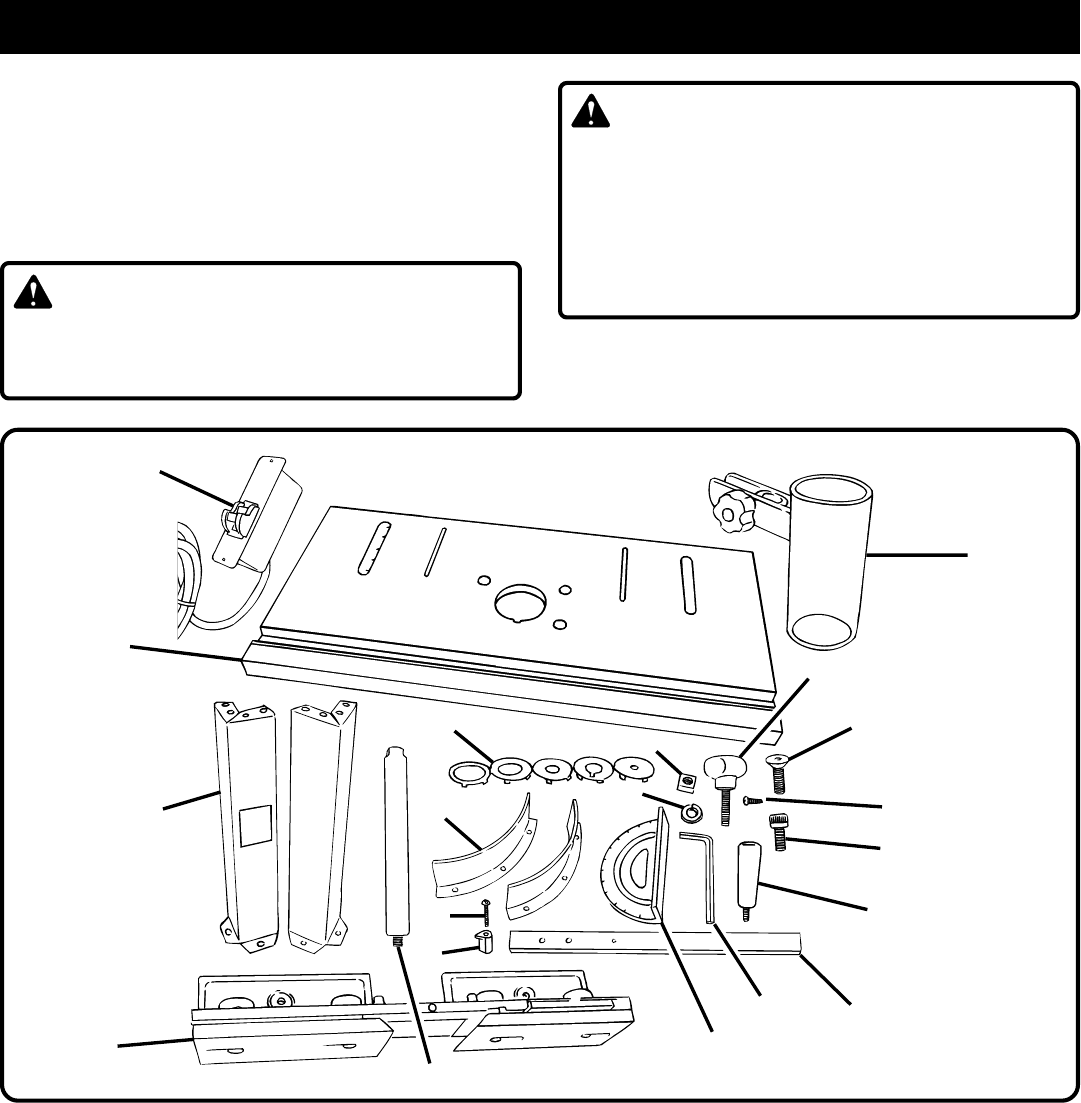
Before assembling your router table check to see that all
parts listed are included.
See Figure 2.
Inspect it carefully
to make sure no breakage or damage has occurred during
shipping. If any parts are damaged or missing, call 1-800-
525-2579 for your nearest RYOBI AUTHORIZED SERVICE
CENTER to obtain replacement parts before attempting to
assemble or use your router table.
UNPACKING
WARNING:
If any parts are damaged or missing, do not use your
router table until the parts are replaced. Failure to do so
could result in possible serious personal injury.
1. Table leg (4)
2. 1/4-20 x 1/2 in. socket head cap screw
(22)
3. 3/16 in. hex key (1)
4. Lock washer (16)
5. Switch box assembly (1)
6. Lower guard (2)
7. 5/16-18 x 1 in. phillips head
machine screw (3)
8. #6 thread cutting screw (2)
9. Fence assembly (1)
10. 1/4-20 square nut (2)
11. Fence lock knob (2)
12. Guard post (1)
13. Guard/dust cover assembly (1)
14. Miter gauge bar (1)
15. Miter gauge (1)
16. Throat plate (5)
17. Miter gauge knob (1)
18. Router table surface (1)
19. #6-32 x 5/8 in. pan head
phillips machine screw (1)
20. Miter gauge pointer (1)
21. Operator’s manual (not
shown) (1)
22. Warranty registration card
(not shown) (1)
WARNING:
To prevent accidental starting or electrical shock that
could cause possible serious personal injury, assemble
all parts to your router table before connecting it to power
supply. Neither the router nor the table should be
connected to power supply when you are assembling
parts, making adjustments, installing or removing cutters,
cleaning, or when not in use.
18
12
Fig. 2
1
2
3
4
5
6
7
8
9
10
11
13
14
15
16
17
19
20