


Page 9
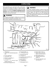
GUARD/DUST COVER ASSEMBLY
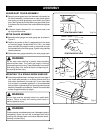
Securely screw guard post into threaded hole located on
the fence assembly. Loosen knob on clear plastic guard/
dust cover and slide guard/dust cover down over guard
post.
See Figures 8a and 8b
. Make sure guard/dust cover
is centered over the throat of the router table and retighten
knob.
If desired, insert a standard 2-1/4 in. vacuum hose in the
top of guard/dust cover.
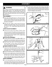
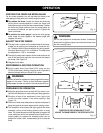
MITER GAUGE ASSEMBLY
Assemble miter gauge and miter gauge bar as shown in
Figure 9.
Position the pointer so that it is perpendicular to the scale
on the miter gauge. Locate the #6-32 x 5/8 in. pan head
screw and feed it through the hole in the pointer and into
the threaded hole in the miter gauge. Tighten using a phillips
head screwdriver.
Slide entire miter gauge assembly into miter gauge track.
WARNING:
Do not wear loose clothing or jewelry when operating
table-mounted router. They could get caught in moving
parts causing serious injury. Keep head away from router
and routing area. Hair could be drawn into spinning cut-
ter causing serious injury.
MOUNTING TO A STABLE WORK SURFACE
Using the predrilled holes in the legs, mount the four legs of
your router table securely on a sturdy surface such as a
work stand, workbench or counter top. If your router table
is to be used in a portable application, it is recommended
that you fasten it permanently to a mounting board that can
be easily clamped to a workbench. Position the router table
surface at approximately hip height.
WARNING:
All four legs must be securely bolted to a stable work
surface. Failure to heed this warning could result in
serious personal injury.
WARNING:
Check extension cords before each use. If damaged, replace
immediately. Never use tool with a damaged cord since
touching the damaged area could cause electrical shock,
resulting in serious injury.
ASSEMBLY
Fig. 9
Fig. 8b
Fig. 8a
Fig. 7b
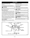
VIEW FROM BELOW TABLE
Fig. 7a
VIEW FROM ABOVE TABLE