


Page 11
45
30
15
30
45
31.62
2
2
.5
31.62
2
2
.5
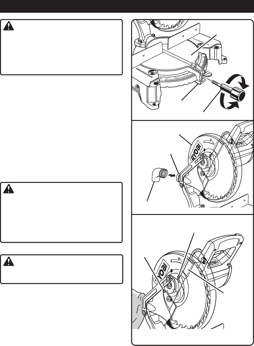
Fig. 7
Fig. 9
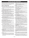
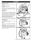
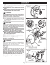
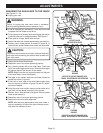
DUST GUIDE
UPPER
BLADE GUARD
EXHAUST
PORT
WARNING:
To prevent accidental starting that could cause possible
serious personal injury, assemble all parts, make sure all
adjustments are complete, and make sure all fasteners
are secure before connecting saw to power supply. Saw
should never be connected to power supply when you are
assembling parts, making adjustments, installing or re-
moving blades, or when not in use.
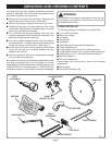
As mentioned previously your saw has been factory as-
sembled and adjusted. The miter lock handle, dust guide or
dust bag, table extensions, stop block, and blade are the
only parts that have to be installed.
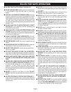
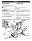
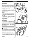
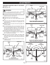
MITER LOCK HANDLE
See Figure 7.
To install the miter lock handle, place the threaded stud on
the end of the miter lock handle into the threaded hole in
the control arm under miter table. Turn clockwise to tighten.
DUST GUIDE
See Figure 8.
To install the dust guide, place the end marked INSERT
over the exhaust port in the upper blade guard. Turn the
guide so that the open end is facing down.
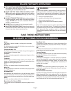
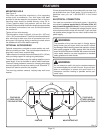
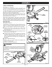
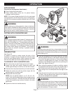
TO INSTALL BLADE
See Figures 9, 10, and 11.
WARNING:
A 10 in. (254 mm) blade is the maximum blade capacity
of your saw. Never use a blade that is too thick to allow
outer blade washer to engage with the flats on the spindle.
Larger blades will come in contact with the blade guards,
while thicker blades will prevent the blade bolt from
securing the blade on the spindle. Either of these situa-
tions could result in a serious accident and can cause
serious personal injury.
■ Unplug your saw.
WARNING:
Failure to unplug your saw could result in accidental
starting causing possible serious personal injury.
■ Raise saw arm.
■ Loosen screw A on the blade bolt cover
.
■ Rotate lower blade guard up and remove screw B. Ro-
tate blade bolt cover up and back to expose the blade
bolt.
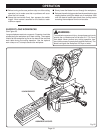
■ Depress the spindle lock button and rotate the blade
bolt until the spindle locks.
See Figure 10.
■ Using the wrench provided, loosen and remove the
blade bolt.
TO
TIGHTEN
CONTROL ARM
TO
LOOSEN
MITER
LOCK HANDLE
ASSEMBLY
SCREW A
SCREW B
MITER
TABLE
Fig. 8
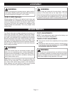
WARNING LABEL