


Page 12
ASSEMBLY
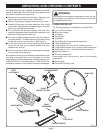
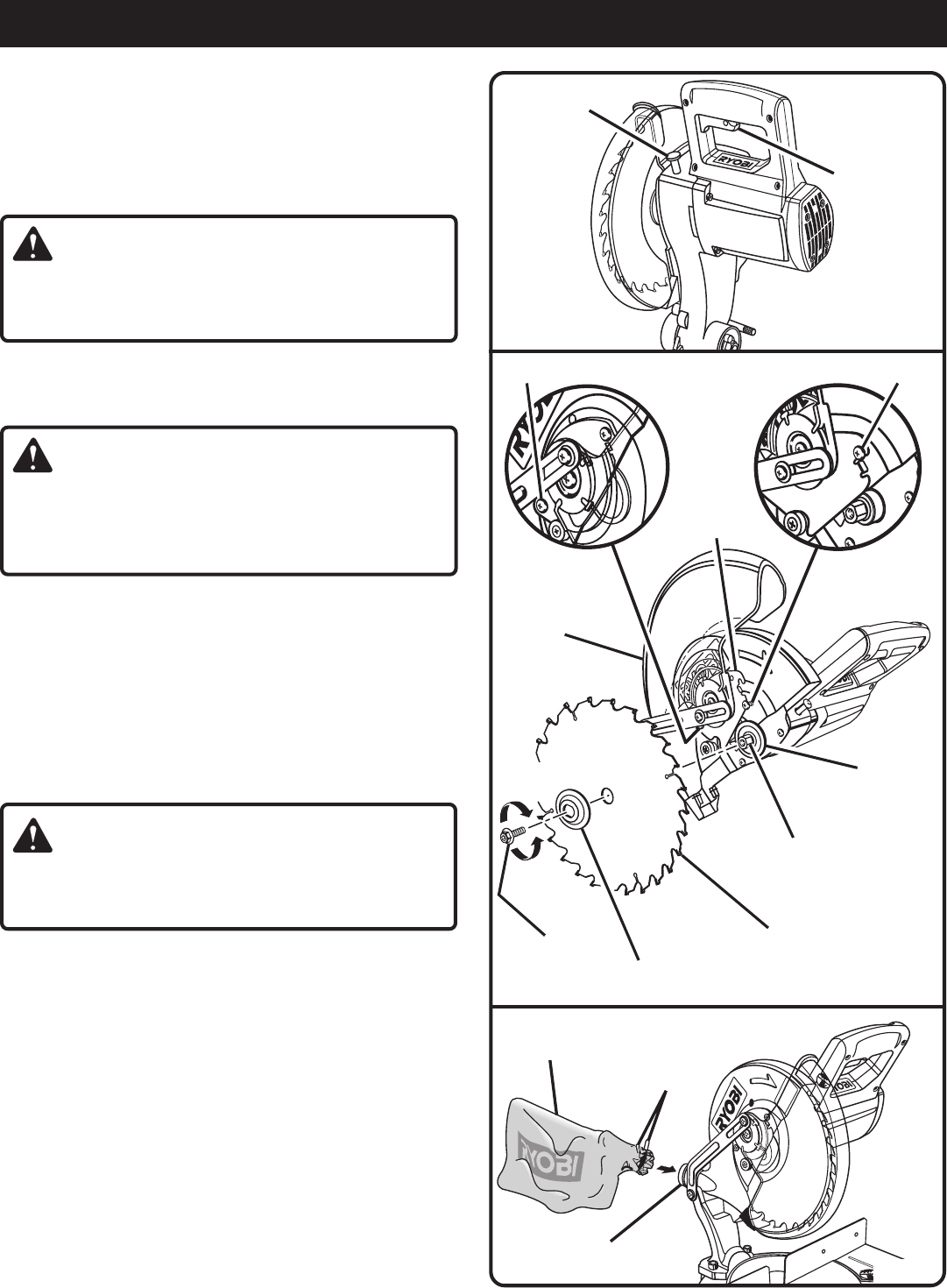
Fig. 10
Fig. 11
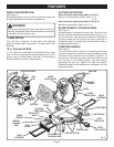
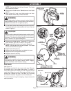
SWITCH
TRIGGER
SPINDLE LOCK
BUTTON
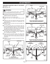
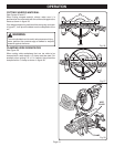
DUST BAG
METAL CLIPS
EXHAUST PORT
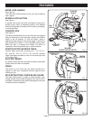
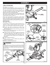
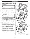
NOTE: The blade bolt has left hand threads. Turn blade
bolt clockwise to loosen.
■ Remove outer blade washer. Do not remove inner blade
washer.
■ Wipe a drop of oil onto inner blade washer and outer
blade washer where they contact the blade.
WARNING:
If inner blade washer has been removed, replace it before
placing blade on spindle. Failure to do so could cause an
accident since blade will not tighten properly.
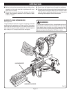
■ Fit saw blade inside lower blade guard and onto spindle.
The blade teeth point downward at the front of saw as
shown in figure 11.
CAUTION:
Always install the blade with the blade teeth and the arrow
printed on the side of the blade pointing down at the front
of the saw. The direction of blade rotation is also stamped
with an arrow on the upper blade guard.
■ Replace outer blade washer. The double "D" flats on the
blade washers align with the flats on the spindle.
■ Depress spindle lock button and replace blade bolt.
NOTE: The blade bolt has left hand threads. Turn blade
bolt counterclockwise to tighten.
■ Tighten blade bolt securely.
■ Replace the lower blade guard and blade bolt cover.
■ Replace screw B and tighten securely.
■ Retighten screw A securely.
WARNING:
Make sure the spindle lock button is not engaged before
reconnecting saw into power source. Never engage
spindle lock button when blade is rotating.
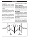
DUST BAG
See Figure 12.
A dust bag is provided for use on your miter saw. It fits over
the exhaust port on the upper blade guard. To install it,
remove dust guide from exhaust port. Then, squeeze the two
metal clips to open the mouth of the bag and slide it on the
exhaust port. Release the clips. The metal ring in the bag
should lock in between the grooves on the exhaust port.
To remove the dust bag for emptying, simply reverse the
above procedure.
LOWER
BLADE GUARD
INNER BLADE
WASHER WITH
DOUBLE "D" FLATS
BLADE
OUTER BLADE WASHER
WITH DOUBLE "D" FLATS
BLADE BOLT
TO
TIGHTEN
TO
LOOSEN
SCREW A
SCREW B
Fig. 12
FLAT (S)
ON SPINDLE
BLADE
BOLT
COVER