


S3F84P4_AN_REV0.00 (PRELIMINARY SPEC) 3 SOFTWARE IMPLEMENTATION
3 SOFTWARE IMPLEMENTATION
S
amsun
g
Con
f
idential
13
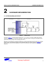
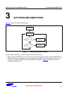
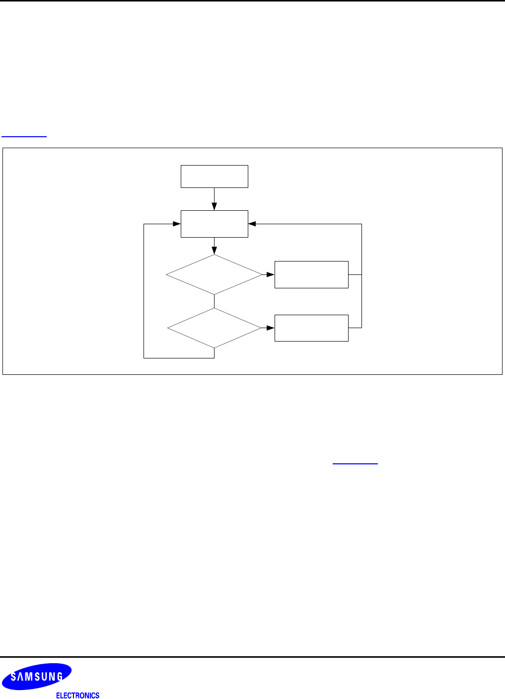
Figure 3-1 shows the software implementation.
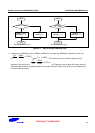
Initialization
Value > max?
ADC sampling
Vale < min?
Decrease PWM
duty cycle
Increase PWM
duty cycle
Figure 3-1 Software Implementation Diagram
Since the PWM in S3F84P4 is 6+6 type, it affects the software in two ways.
Way to change the PWM duty cycle: The duty cycle is the result of both the register values of PWMDATA and
PWMEX. Therefore, any increase or decrease in register from PWMDATA will not change the duty cycle. For
more details on register PWMEX, refer to the S3F84P4 User’s Manual. Figure
3-2 shows the right way to
change the PWM duty cycle.