


S3F84P4_AN_REV0.00 (PRELIMINARY SPEC) 1 OVERVIEW OF HPLED LIGHTING CONTROL SYSTEM
1.3.1 BUCK CIRCUIT
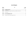
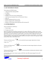
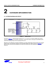
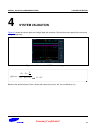
Figure 1-2 Simplified Buck Circuit
Buck circuit works when a switch signal turns on the transistor (Q). The DC power then starts to charge the coil
(L). When the current reaches a predefined level, change the transistor state from On to Off using the switch
signal. At this time, since the coil will have inertia to keep the current direction, the load still can be powered with a
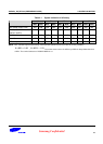
freewheeling diode until the switch signal turns on the transistor again. The resulting current is continuous but
alternating (see
S
amsun
g
Con
f
idential
9
Figure 1-3 for more details).
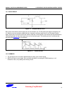
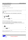
Figure 1-3 Current on load
1.3.2 SUMMARY
The average current over load is determined by the duty cycle of switch signal.
SMPS can lead to current ripple. But it could be alleviated by increasing the PWM frequency or coil
inductance value, or by adding extra filtering circuits.