


S3F84P4_AN_REV0.00 (PRELIMINARY SPEC) 1 OVERVIEW OF HPLED LIGHTING CONTROL SYSTEM
1.2 KEY FEATURES OF S3F84P4
The key features in S3F84P4 include:
4 kbyte Flash ROM or 208 Byte SRAM
6+6 PWM x 1
10-bit ADC x 4
8-bit Basic Timer (can be used as watchdog timer)
16-bit Timer0 (can be used as Timer A or B, the two 8-bit Timers )
EXINT X 2
Supports Configurable LVR (2.2/ 3.0/ 3.9V)
Supports Configurable RC (1M/ 8MHz @5V)
Supports six IOs (maximum) when using internal LVR and internal RC
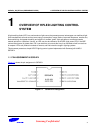
1.3 SYSTEM PRINCIPLE
The two considerations for HPLED are:
1. Forward voltage
2. Constant control current
Different LED applications have different characteristics. For instance, LEDs come in different colors. In some
cases, manufacturers of the LED applications might also differ. Even if the LED applications come from the same
manufacturer, it can lead to differences in forward voltage. In such cases, constant voltage power cannot work.
Different LED applications should select different power suppliers according to its characteristics. For instance, by
considering efficiency, switch module power supplier (SMPS) can be chosen for different LED applications. SMPS
consists of Buck, Boost, or Buck-Boost circuits.
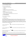
O
I
V
D
V
The duty cycl
e of Buck circuit is . It is only used when the power supply is high
er than the forward
voltage, that is, .
OI
VV
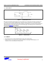
OI
O
VV
D
V
The duty cycl
e of Boost circuit is . It is only used when the forward voltage is higher than the power
s
upply, that is, .
OI
VV
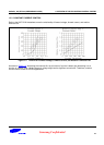
O
O
V
D
VV
I
The duty cycl
e of Buck-Boost circuit is . It can be used without considering the relationship of power
sup
ply and forward voltage.
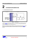
In this application, buck circuit is chosen to power a HKP-D1W1 white LED (forward voltage 3.5V) with a DC
power source of 5V.
S
amsun
g
Con
f
idential
8