


ENGLISH
Explanation of general view
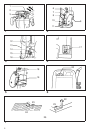
1 Wrench
2 Router bit
3 Shaft lock
4 Tighten
5 Loosen
6 Nylon nut
7 Stopper pole
8 Fast-feed button
9 Lock lever
10 Adjusting hex bolt
11 Stopper
12 Stopper pole
13 Chip deflector
14 Adjusting hex bolt
15 Hex nut
16 Stopper
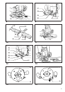
17 Switch lever
18 Lock-off button
19 Switch trigger
20 Speed change knob
21 Workpiece
22 Bit revolving direction
23 Feed direction
24 View from the top of the tool
25 Correct bit feed direction
26 Straight guide
27 Guide holder
28 Fine adjusting screw
29 Wing bolt (B)
30 Wing bolt (A)
31 Stright guide
32 More than 15 mm
33 Straight guide
34 Wood
35 Trimmer guide
36 Wing bolt (A)
37 Guide roller
38 Guide holder
39 Fine adjusting screw
40 Wing bolt (B)
41 Wing bolt (C)
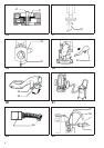
42 Trimmer guide
43 Templet guide
44 Screw
45 Templet guide
46 Lock plate lever
47 Bit
48 Base
49 Templet
50 Workpiece
51 Templet guide
52 Vaccum head
53 Screws
54 Support
55 Lock lever
56 Limit mark
57 Brush holder cap
58 Screwdriver
SPECIFICATIONS
Model 3612 3612C
Collet capacity .................................................................. 12 mm or 1/2″ 12 mm or 1/2″
Plunge capacity ................................................................ 0 – 60 mm 0 – 60 mm
No load speed (min
–1
) ..................................................... 22,000 9,000 – 23,000
Overall heigth .................................................................... 297 mm 297 mm
Base diameter ................................................................... 160 mm 160 mm
Net weight ........................................................................ 5.8 kg 6.0 kg
•
Due to the continuing program of research and devel-
opment, the specifications herein are subject to change
without prior notice.
•
Note: Specifications may differ from country to country.
Power supply
The tool should be connected only to a power supply of
the same voltage as indicated on the nameplate, and can
only be operated on single-phase AC supply. They are
double-insulated in accordance with European Standard
and can, therefore, also be used from sockets without
earth wire.
For public low-voltage distribution systems of
between 220 V and 250 V
Switching operations of electric apparatus cause voltage
fluctuations. The operation of this device under unfavor-
able mains conditions can have adverse effects to the
operation of other equipment. With a mains impedance
equal or less than 0.32 Ohms it can be presumed that
there will be no negative effects.
The mains socket used for this device must be protected
with a fuse or protective circuit breaker having slow
tripping characteristics.
Safety hints
For your own safety, please refer to enclosed safety
instructions.
ADDITIONAL SAFETY RULES ENB033-2
1. Hold tool by insulated gripping surfaces when
performing an operation where the cutting tool
may contact hidden wiring or its own cord. Con-
tact with a ‘‘live’’ wire will make exposed metal
parts of the tool ‘‘live’’ and shock the operator.
2. Wear hearing protection during extended period
of operation.
3. Handle the bits very carefully.
4. Check the bit carefully for cracks or damage
before operation. Replace cracked or damaged bit
immediately.
5. Avoid cutting nails. Inspect for and remove all
nails from the workpiece before operation.
6. Hold the tool firmly with both hands.
7. Keep hands away from rotating parts.
8. Make sure the bit is not contacting the workpiece
before the switch is turned on.
9. Before using the tool on an actual workpiece, let it
run for a while. Watch for vibration or wobbling
that could indicate improperly installed bit.
10. Be careful of the bit rotating direction and the
feed direction.
11. Do not leave the tool running. Operate the tool
only when hand-held.
12. Always switch off and wait for the bit to come to a
complete stop before removing the tool from
workpiece.
13. Do not touch the bit immediately after operation;
it may be extremely hot and could burn your skin.
14. Always lead the power supply cord away from the
tool towards the rear.
6