


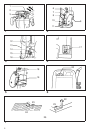
Straight guide
When using the straight guide, be sure to install it on the
right side in the feed direction. (Fig. 8)
Install the straight guide on the guide holder with the wing
bolt (B). Insert the guide holder into the holes in the tool
base and tighten the wing bolt (A). To adjust the distance
between the bit and the straight guide, loosen the wing
bolt (B) and turn the fine adjusting screw (1.5 mm per
turn). (Fig. 9)
Wider straight guide of desired dimensions may be using
the convenient holes in the guide to bolt on extra pieces
of wood.
When using a large diameter bit, attach pieces of wood to
the straight guide which have a thickness of more than
15 mm to prevent the bit from striking the straight guide.
(Fig. 10)
Trimmer guide
When using the trimmer guide, be sure to install it on the
right side in the feed direction. (Fig. 11)
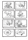
Install the trimmer guide on the guide holder with the wing
bolt (B). Insert the guide holder into the holes in the tool
base and tighten the wing bolt (A). To adjust the distance
between the bit and the trimmer guide, loosen the wing
bolt (B) and turn the fine adjusting screw (1.5 mm per
turn). When adjusting the guide roller up or down, loosen
the wing bolt (C). (Fig. 12)
Templet guide
For tool without lock plate
The templet guide provides a sleeve through which the bit
passes, allowing use of the router with templet patterns.
(Fig. 13)
To install the templet guide, loosen the screws on the tool
base, insert the templet guide and then tighten the
screws. (Fig. 14)
Secure the templet to the workpiece. Place the tool on the
templet and move the tool with the templet guide sliding
along the side of the templet. (Fig. 16)
For tool with lock plate
The templet guide provides a sleeve through which the bit
passes, allowing use of the router with templet patterns.
(Fig. 13)
To install the templet guide, pull the lock plate lever and
insert the templet guide. (Fig. 15)
Secure the templet to the workpiece. Place the tool on the
templet and move the tool with the templet guide sliding
along the side of the templet. (Fig. 16)
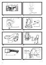
Dust extraction
For tool without lock plate
Use the vacuum head for dust extraction. Install the
vacuum head on the tool base using the two screws.
(Fig. 17 & 18)
Then connect a vacuum cleaner to the vacuum head.
(Fig. 21)
For tool with lock plate
Use the vacuum head for dust extraction. To install the
vacuum head, raise the lock lever on it. Place the vacuum
head on the tool base so that its top will be caught in the
hook on the tool base. Insert the supports on the vacuum
head into the hooks on the front of the tool base. Push
down the lock lever onto the tool base. (Fig. 19 & 20)
Then connect a vacuum cleaner to the vacuum head.
(Fig. 21)
To remove the vacuum head, raise the lock lever. Pull the
vacuum head out of the tool base while holding the
supports between thumb and finger.
MAINTENANCE
CAUTION:
Always be sure that the tool is switched off and unplugged
before carrying out any work on the tool.
Replacement of carbon brushes (Fig. 22 & 23)
Replace carbon brushes when they are worn down to the
limit mark. Both identical carbon brushes should be
replaced at the same time.
To maintain product safety and reliability, repairs, main-
tenance or adjustment should be carried out by Makita
Authorized Service Center.
8