


15. Do not smear the tool base carelessly with thin-
ner, gasoline, oil or the like.
They may cause cracks in the tool base.
16. Draw attention to the need to use cutters of the
correct shank diameter and which are suitable for
the speed of the tool.
SAVE THESE INSTRUCTIONS.
OPERATING INSTRUCTIONS
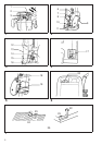
Installing or removing the router bit (Fig. 1)
Important:
Always be sure that the tool is switched off and unplugged
from the supply outlet before installing or removing the
router bit.
Insert the router bit all the way into the collet. Press the
shaft lock to keep the shaft stationary and use the wrench
to tighten the collet nut securely. When using router bits
with smaller shank diameter, first mount the appropriate
collet, then install the bit as described above.
CAUTION:
•
Do not tighten the collet without inserting a router bit.
•
Use always a collet which is suitable for the shank
diameter of the router bit.
•
Use only router bits of which the maximum speed, as
indicated on the bit, does exceed the maximum speed
of the router.
Adjusting the depth of cut (Fig. 2)
Important:
Always be sure that the tool is switched off and unplugged
before adjusting the depth of cut.
Place the tool on a flat surface. Loosen the lock lever and
lower the tool body until the bit just touches the flat
surface. Press the lock lever down to lock the tool body.
While pressing the fast-feed button, move the stopper
pole up or down until the desired depth of cut is obtained.
Minute depth adjustments can be obtained by turning the
stopper pole (1.5 mm per turn).
CAUTION:
The depth of cut should not be more than 20 mm at a
pass when cutting grooves. For extra-deep grooving
operations, make two or three passes with progressively
deeper bit settings.
Nylon nut (Fig. 2)
The upper limit of the tool body can be adjusted by turning
the nylon nut. Do not lower the nylon nut too low. The bit
will protrude dangerously.
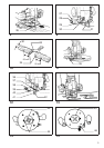
Stopper (Fig. 3)
As the rotary stopper has three adjusting hex bolts, you
can easily obtain three different depths of cut without
readjusting the stopper pole. To adjust the hex bolts,
loosen the hex nuts on them and turn the hex bolts. After
obtaining the desired position, tighten the hex nuts to
secure the hex bolts.
Switching ON and OFF
For tool without lock-off button (Fig. 4)
CAUTION:
Make sure that the shaft lock is released before the switch
is turned on.
To switch on, move the switch lever to the ‘‘ON’’ position.
To switch off, move the switch lever to the ‘‘OFF’’ position.
For tool with lock-off button (Fig. 5)
CAUTION:
•
Before plugging in the tool, always check to see that the
switch trigger actuates properly and returns to the
‘‘OFF’’ position when released.
•
Make sure that the shaft lock is released before the
switch is turned on.
To switch on, push the lock-off button and at the same
time press the trigger.
To switch off, release the trigger.
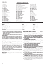
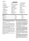
Speed change knob (Fig. 6)
For 3612C only
The tool speed can be infinitely adjusted between 9,000
rpm and 23,000 rpm by turning the speed change knob.
This allows the ideal speed to be selected for optimum
material processing, i.e. the speed can be correctly
adjusted to suit the material and bit diameter. Refer to the
table below for relationship between the number settings
on the speed change knob and approx. tool speed.
Number RPM
1 9,000
2 12,000
3 15,000
4 19,000
5 23,000
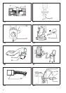
Operation (Fig. 7)
Place the tool on the workpiece and switch on. Release
the lock lever and slowly lower the tool onto the workpiece
until preset routing depth is reached. Move the tool
forward using both hands. When cutting edges, the
workpiece surface should be on the left side of the bit in
the feed direction as shown in Fig. 7.
7