


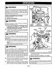
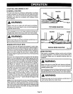
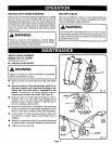
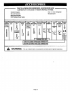

ROUTING WITH GUIDE BUSHINGS
When using the Template Guide Bushings Item No. 9-25082
with your router, you must visually center the bit with the
bushing before beginning your cut. You r router subbase may
be adjusted by loosening the screws holding the subbase to
your router. Be sure clamping lever is locked before center-
ing bit in bushing. After centering bit with bushing, tighten
screws firmly.
WARNING:
Failure to center bit with bushing or to firmly tighten
screws after centering could cause bit to come in contact
with bushing resulting in serious injury.
i
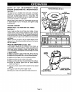
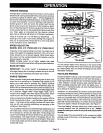
ROUTER TABLES
The use of Craftsman routers on router tables offered by
other manufacturers has not been investigated for compli-
ance with applicable safety standards.
WARNING:
Do not use with router tables that fail to conform to safe
wood working practices and offer proper guarding for the
cutter. Failure to comply can result in an accident causing
possible serious injury.
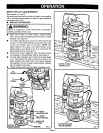
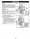
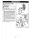
SWITCH REPLACEMENT
(MODEL NO. 315.175040)
See Figures 16and 17.
• UNPLUG YOUR ROUTER.
WARNING:
Failure to unplug your router could result in accidental
starting causing serious injury.
Remove screws (A) and handle cover (B). See Figure
16.
Note the location of the molded bend relief (C) on
the power handle cord. Also note all wiring in the
handle and how each lead is connected to the
switch. Connections and wiring position must be
identical when installing new switch. See Figure 16.
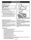
Remove leads from switch (D) by inserting a 1/32 in.
diameter nail or pin into switch lead receptacle and
pulling on lead as shown in figure 17. Remove nail or
pin with a twisting, pulling motion.
Make lead connections to new switch. Push each lead
as far as possible into proper switch receptacle. Pull on
leads to check lead connections with lead receptacles.
Locate switch in handle and place leads so they won't
be pinched or contact screws when handle cover is
replaced.
Make sure molded bend relief (C) is correctly positioned
in switch handle, then replace handle cover and screws.
Tighten all screws securely.
A
SWITCH 1/32IN. DIAMETER
NAIL ORPIN
Fig. 16
Page 17