


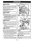

SWITCH REPLACEMENT (CONTINUED)
(MODEL NOS. 315.175050 AND 315.175060)
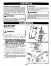
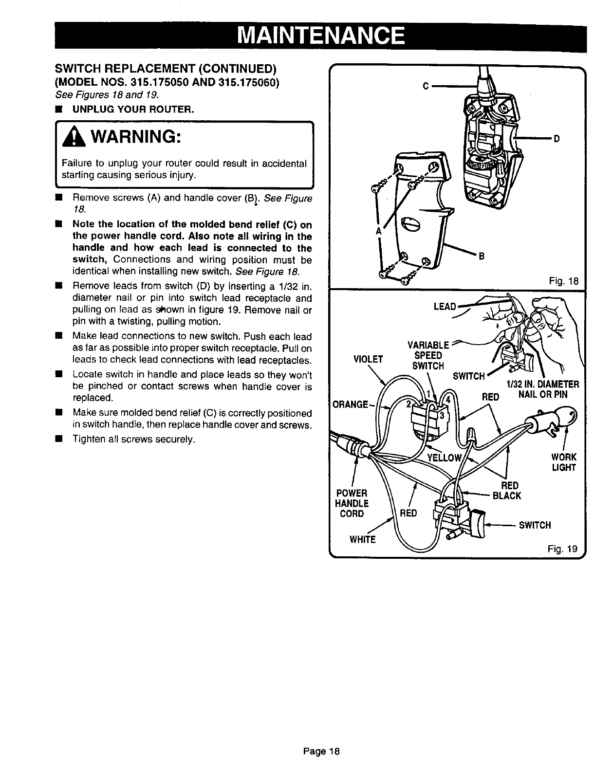
See Figures 18 and 19.
• UNPLUG YOUR ROUTER.
WARNING: 1
Failure to unplug your router could result in accidental
starting causing serious injury.
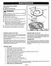
Remove screws (A) and handle cover (Bl, See Figure
18.
Note the location of the molded bend relief (C) on
the power handle cord. Also note all wiring in the
handle and how each lead is connected to the
switch, Connections and wiring position must be
identical when installing new switch. See Figure 18.
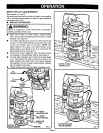
• Remove leads from switch (D) by inserting a 1/32 in.
diameter nail or pin into switch lead receptacle and
pulling on lead as sRown in figure 19. Remove nail or
pin with a twisting, pulling motion.
• Make lead connections to new switch. Push each lead
as far as possible into proper switch receptacle. Pull on
leads to check lead connections with lead receptacles.
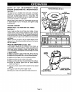
• Locate switch in handle and place leads so they won't
be pinched or contact screws when handle cover is
replaced.
• Make sure molded bend relief (C) is correctly positioned
in switch handle, then replace handle cover and screws.
• Tighten all screws securely.
VIOLET
c
VARIABLE
SPEED
D
Fig. 18
Fig. 19
Page 18