


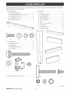

Assembly is best done in the area where the saw will
be used. When you remove the saw and hardware
from the packing materials, carefully check the items
with the Loose Parts list. If you are unsure about the
description of any part, refer to their illustrations. For
your convenience, all fasteners have been drawn
actual size. If any parts are missing, delay assembling
until you have obtained the missing part(s).
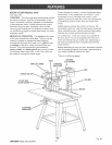
Your radial arm saw is capable of a wide variety of
operations, and thus requires a number of initial setup
adjustments. However, once the saw is set up, you
can check your saw in about ten minutes and correct
any misalignment with the procedures in the Adjust-
ment section.
CAUTION: Perform all the procedures in both
the Assembly and Adjustments sections before
using the saw. Run a check on your saw
frequently, referring to the Adjustments section.
Failure to perform the adjustments in the initial
set up or on a frequent basis can result in poor
performance or machine damage.
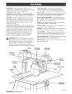
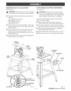
ASSEMBUNG LEG STAND
See Figures IOA - 10C.
[] Take the following hardware from the hardware
bags in the leg stand carton:
40 truss head screws (1/4-20 x 5/8 in.)
40 star washers (114 in.)
40 hex nuts (1/4-20)
[] Take the following hardware from the remaining
hardware bags in the leg stand carton:
4 leveling feet
8 large hex nuts (3/8-16)
[] Obtain four legs and eight braces from the leg
stand carton. See the Loose Parts section.
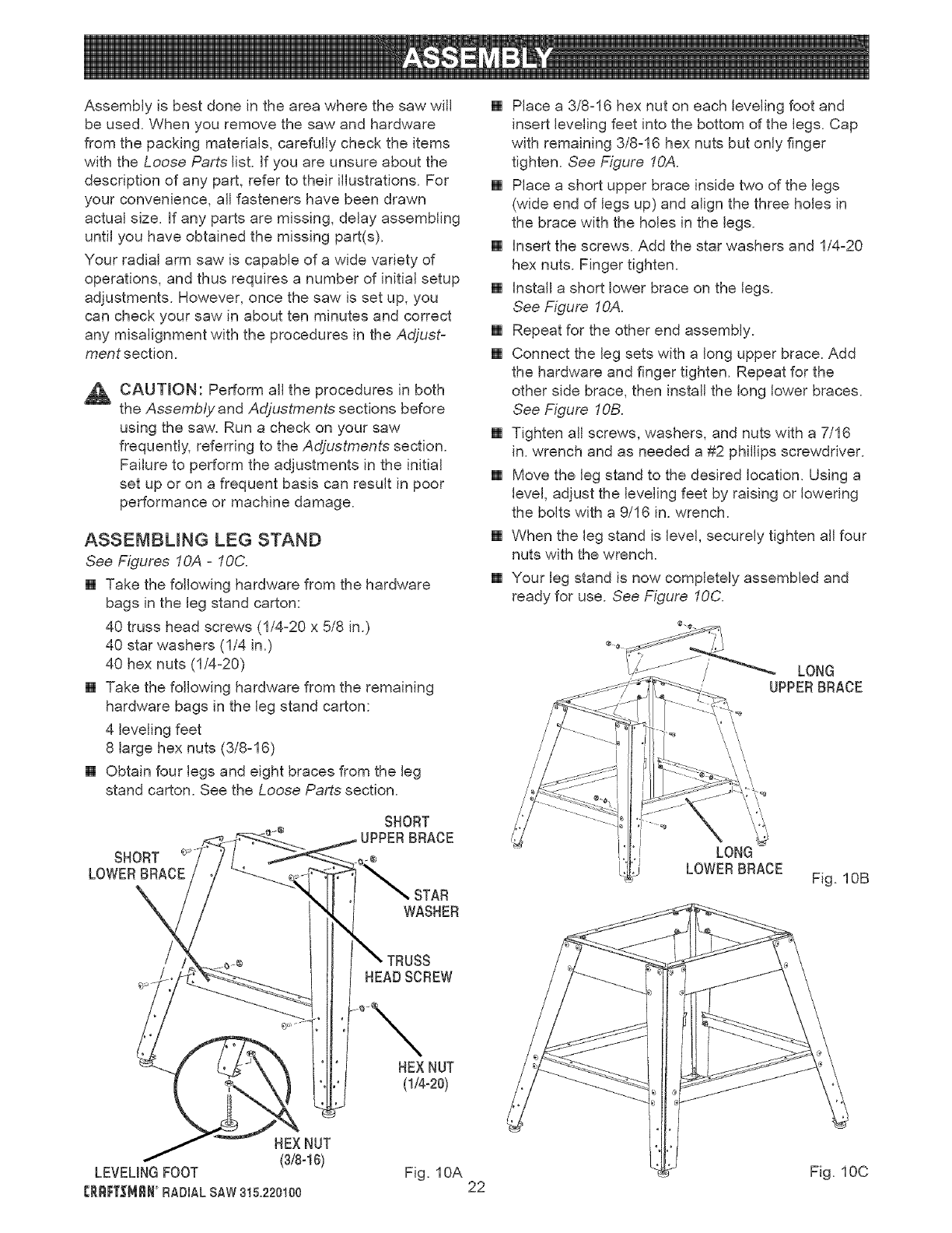
SHORT
LOWERBRACE
SHORT
BRACE
_TAR
WASHER
[] Place a 3/8-16 hex nut on each leveling foot and
insert leveling feet into the bottom of the legs. Cap
with remaining 3/8-16 hex nuts but only finger
tighten. See Figure fOA.
[] Place a short upper brace inside two of the legs
(wide end of legs up) and align the three holes in
the brace with the holes in the legs.
[] Insert the screws. Add the star washers and 1/4-20
hex nuts. Finger tighten.
[] Install a short lower brace on the legs.
See Figure fOA.
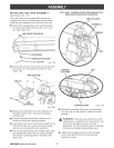
[] Repeat for the other end assembly.
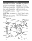
[] Connect the leg sets with a long upper brace. Add
the hardware and finger tighten. Repeat for the
other side brace, then install the long lower braces.
See Figure fOB.
[] Tighten all screws, washers, and nuts with a 7/16
in. wrench and as needed a #2 phillips screwdriver.
[] Move the leg stand to the desired location. Using a
level, adjust the leveling feet by raising or lowering
the bolts with a 9/16 in. wrench.
[] When the leg stand is level, securely tighten all four
nuts with the wrench.
[] Your leg stand is now completely assembled and
ready for use. See Figure 10C.
UPPERBRACE
\' /
\ \
\/ //
'\ \
LONG
LOWERBRACE
Fig. 10B
TRUSS
HEADSCREW
HEXNUT
(lb-20)
HEXNUT
(3/8-16)
LEVELINGFOOT
CRRFT_MRNRADIALSAW3t5.220100
Fig. 10A
22
Fig. 10C