


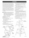
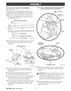
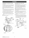
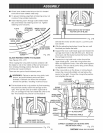

TiGHTENiNG THE ARM AND COLUMN
See Figure 19.
There should be no play, vertical or horizontal, in the
arm relative to the column. If you can move the arm
up, down or sideways when the arm lock is unlocked,
use the following steps to tighten the arm.
Note: The arm should pivot only when the arm lock
knob is unlocked and pulled forward to compress the
spring.
[] Using a phiiJips screwdriver, remove the rear cover
screws (2) and rear cover from the back of the arm.
This uncovers the bolts on the column.
[] Tighten the top two bolts evenly until the arm is firm
and there is no vertical or horizontal movement.
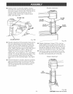
[] Also check the two bottom hex nuts. It is not
necessary to tighten them as tight as the upper
bolts. However they should be tightened even and
snug.
[] Replace the rear cover and rear cover screws.
[] Tighten screws securely.
REAR
COVERSCREWS
REAR
COVER
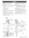
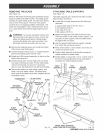
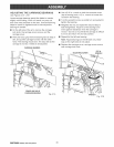
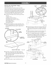
ADJUSTING THE COLUMN TUBE
See fLgures 20A - 20D.
The purpose of this procedure is to check whether the
inner coJumn tube is snug in the housing and to
remove any looseness. Looseness could result in a
poor cut or difficulty in elevating the carriage. The
coJumn tube is the upper portion of the column and
extends from the column support.
Note: It is critical to remove alJ looseness with this
procedure. If this procedure is not done correctly,
folJowing adjustments will be wrong and could result in
machine damage.
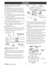
This procedure checks both the elevating action and
the rotating action. If a check does not show loose-
ness, do not perform the adjustment.
[] if the arm is not at 0° (straight forward), release the
arm lock knob, set the arm, and reqock the arm
lock knob.
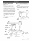
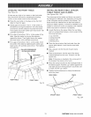
[] Elevation Check: To check the elevation move-
ment, place your hand under the front of the radial
arm. Press upward on the radial arm. There should
be minimal play between the column tube and the
column support. The whole assembly should move
as one. See Figure 20A.
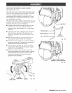
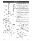
HEXBOLT (2)
COLUMN
SUPPORT
Fig. 20A
HEX NUT(2)
Fig. 19
CRRF[_MRN RADIALSAW 315.220100 28