


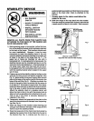
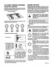
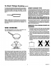
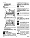
STABILITY DEVICE
• ALL RANGES
CAN TIP
• INJURY TO PERSONS
COULD RESULT
• INSTALL ANTI-TIP
DEVICES PACKED
WITH RANGE
• SEE INSTALLATION
INSTRUCTIONS
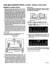
pulled as tlg ht as possible and that there Is no excess
slack In the chain after chain is attached to the
bracket.
Excess slack in the chain could allow the
range to tip over.
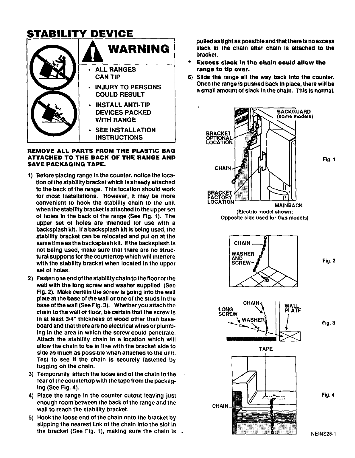
6) Slide the range all the way back Into the counter.
Once the range is pushed back in place, there will be
a small amount of slack in the chain. This is normal.
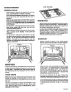
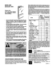
BACKGUARD
BRACKET
OP_ONAL
LOCATION
REMOVE ALL PARTS FROM THE PLASTIC BAG
ATTACHED TO THE BACK OF THE RANGE AND
SAVE PACKAGING TAPE.
Fig. 1
1) Before placing range In the counter, notice the loca-
tion of the stability bracket which is already attached
to the back ot the range. This location should work
for most installations. However, it may be more
convenient to hook the stability chain to the unit
when the stability bracket isattached to the upper set
of holes in the back of the range (See Fig. 1). The
upper set of holes are Intended for use with a
backsplash kit. If a backsplash kit is being used, the
stability bracket can be relocated and put on at the
same time as the backsplash kit. Ifthe backsplash is
not being used, make sure that there are no struc-
tural supports for the countertop which will Interlere
with the stability bracket when located in the upper
set of holes.
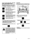
2) Fasten one end of the stability chain to the floor or the
wall with the long screw and washer supplied (See
Fig. 2). Make certain the screw is going into the wall
plate at the base of the wall or one of the studs In the
base of the wall (See Fig. 3). Whether you attach the
chain to the wall or floor, be certain that the screw Is
in at least 3/4" thickness of wood other than base-
board and that there are no electrical wires or plumb-
ing in the area In which the screw could penetrate.
Attach the stability chain in a location which will
allow the chain to be in line with the bracket side to
side as much as possible when attached to the unit.
Test to see If the chain is securely fastened by
tugging on the chain.
3) Temporarily attach the loose end of the chain to the
rear ol the countertop with the tape from the packag-
ing (See Fig. 4).
4) Place the range In the counter cutout leaving just
enough room between the back of the range and the
wall to reach the stability bracket.
5) Hook the loose end of the chain onto the bracket by
slipping the nearest link of the chain into the slot in
the bracket (See Fig. 1), making sure the chain is 1
FACTORY
LOCA_ON
MAINBACK
(Ele_ric modelshown;
OpposltesideusedforGas models)
CHAIN--
WASHER
AND
SCREW-
CHAIN
CHAIN_ I [ WALL
\\ II P ATE
_x I WASHER_ J] /
TAPE
Fig. 2
Fig. 3
Fig. 4
NEINS28-1