


-27-
M1109 Combo Lathe/Mill
OPERATIONS
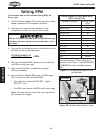
The carriage has longitudinal and cross slide power feed
capabilities. All directions reverse when spindle rotation
is reversed.
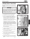
To set and engage the power feed, do these steps:
1. DISCONNECT THE LATHE/MILL FROM POWER!
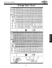
2. Refer to the Change Gear Chart on Page 29, or
the chart on the inside of the change gear door to
determine the needed combination of gears and
which spindle location to install each gear on.
See Figure 39 for the gear installation locations on
the lathe that are referenced by the chart
.
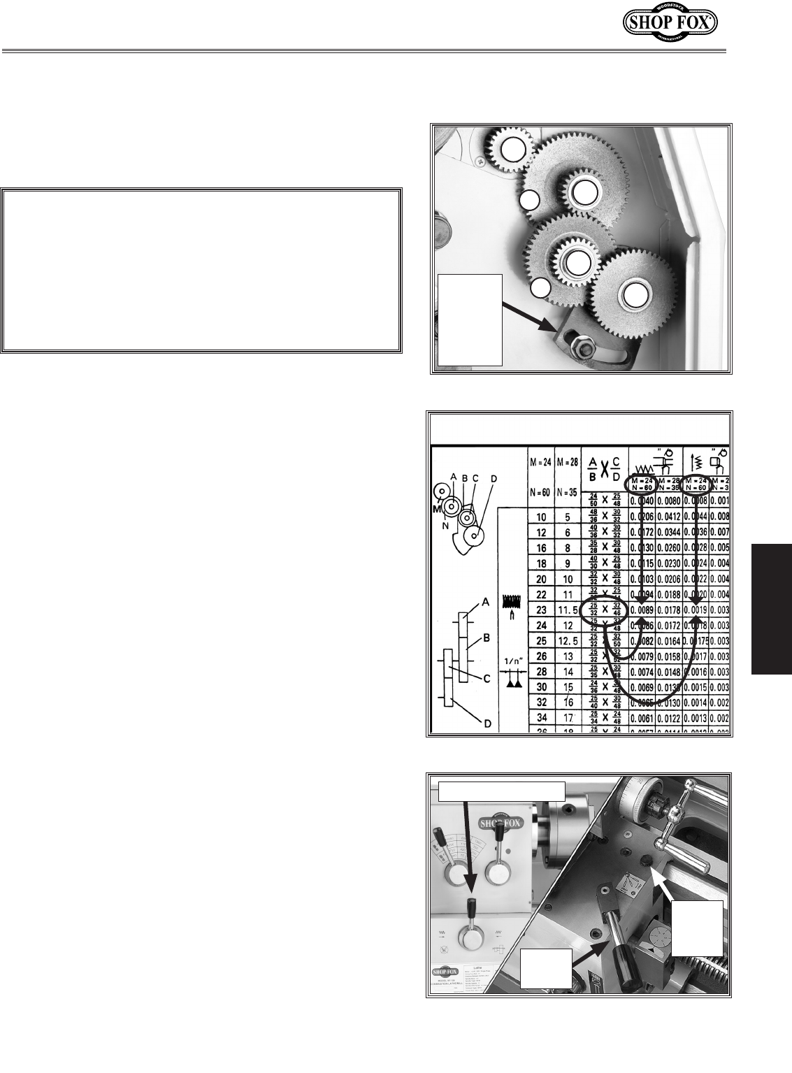
See Figure 40 for examples of how certain gear
combinations can achieve your needed longitudinal
and cross feed rates. For example: The chart shows
that 0.0089" of longitudinal travel per revolution of
lead screw is needed, or 0.0019" of cross travel per
revolution of lead screw is needed.
Note: All change gears are stamped with the num-
ber of teeth they have.
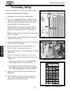
3. Loosen the lash adjuster (Figure 39) and swing the
assembly out of the way.
4. Remove the required E-clips, lubricate, and swap
out the appropriate change gears
.
5. Move the lash adjuster so the gear backlash is at
0.003" to 0.008", and tighten the lock nut
.
6. Use the leadscrew lever to select leadscrew rota-
tion direction
(Figure 41).
7. Loosen the apron lock bolt, and use the feed lever
(Figure 41) to engage the cross feed or longitudinal
feed.
Setting Power Feed Rate
Figure 41. Leadscrew and feed levers.
Figure 39. Change gear locations.
D
C
A
B
N
M
Longitudinal
Feed
Cross
Feed
Inch
Threading
Figure 40. Using the change gear chart.
Lash
Adjuster
and
Lock
Nut
Feed
Lever
Leadscrew Lever
NOTICE
Feed rate is based on spindle RPM. High feed rates
combined with high spindle speeds result in a rapidly
moving carriage or cross slide. Pay close attention
to the feed rate you have chosen and be ready to
disengage the apron. Failure to do this may cause
the carriage to crash into the chuck.
Apron
Lock
Bolt