


-8-
W1681 Buffing Assembly
SETUP
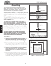
The strongest bench mounting option is a "Through
Mount" where holes are drilled all the way through the
workbench, and hex bolts, washers, and hex nuts are
used to secure the drill press to the workbench.
Another option for mounting is a "Direct Mount" where the
machine is simply secured to the workbench with a lag
screw.
The Model W1681 is designed to mount to a bench top
using (4)
5
⁄16" diameter lag bolts or through bolts, as
shown in Figures 2 & 3.
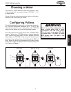
The motor must be mounted either directly below or
behind the Buffing assembly. If the motor is mounted
below the buffing assembly, a hole must be cut in the
bench to allow passage of the V-belt between the buffing
assembly and the motor. If the motor is mounted behind
the buffing assembly, no hole in the bench is needed
because the V-belt will connect to the motor through the
rear casting of the buffing assembly body.
The buffing assembly must be attached to a stable
workbench capable of handling the rigors of a motor
driven machine. Determine if you will be mounting the
motor below or behind the buffing assembly.
Motor Below
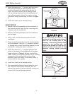
1. Position the buffing assembly on the workbench in
the desired position. Mark the four mounting hole
locations onto the workbench, as shown in Figure 4.
2. Trace around the open area on the inside, bottom
edge of the buffing assembly. This will be the hole
for the V-belt passage to the motor mount beneath.
3. Remove the buffing assembly from the workbench.
Using a jig saw and drill, cut out the V-belt
passage hole and drill the mounting holes into the
workbench.
4. Place the buffing assembly over the mounting holes
in the workbench. Using (4)
5
⁄16" diameter lag bolts
or through bolts, attach the buffing assembly to the
workbench, making sure that it is secure.
Mounting
Machine Base
Workbench
Bolt
Flat Washer
Flat Washer
Lock Washer
Hex Nut
Figure 2. Example of a through mount.
Machine Base
Workbench
Lag Screw
Flat Washer
Figure 3. Example of a direct mount.
4-3/4"
4-1/2"
3/8" Dia.
Front
Figure 4. Mounting bolt layout.
Provided for
reference only.
For best results,
use your machine
as a template for
marking holes