


-33-
W1808/W1809/W1810 Cyclone Dust Collectors
OPERATIONS
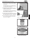
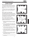
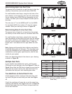
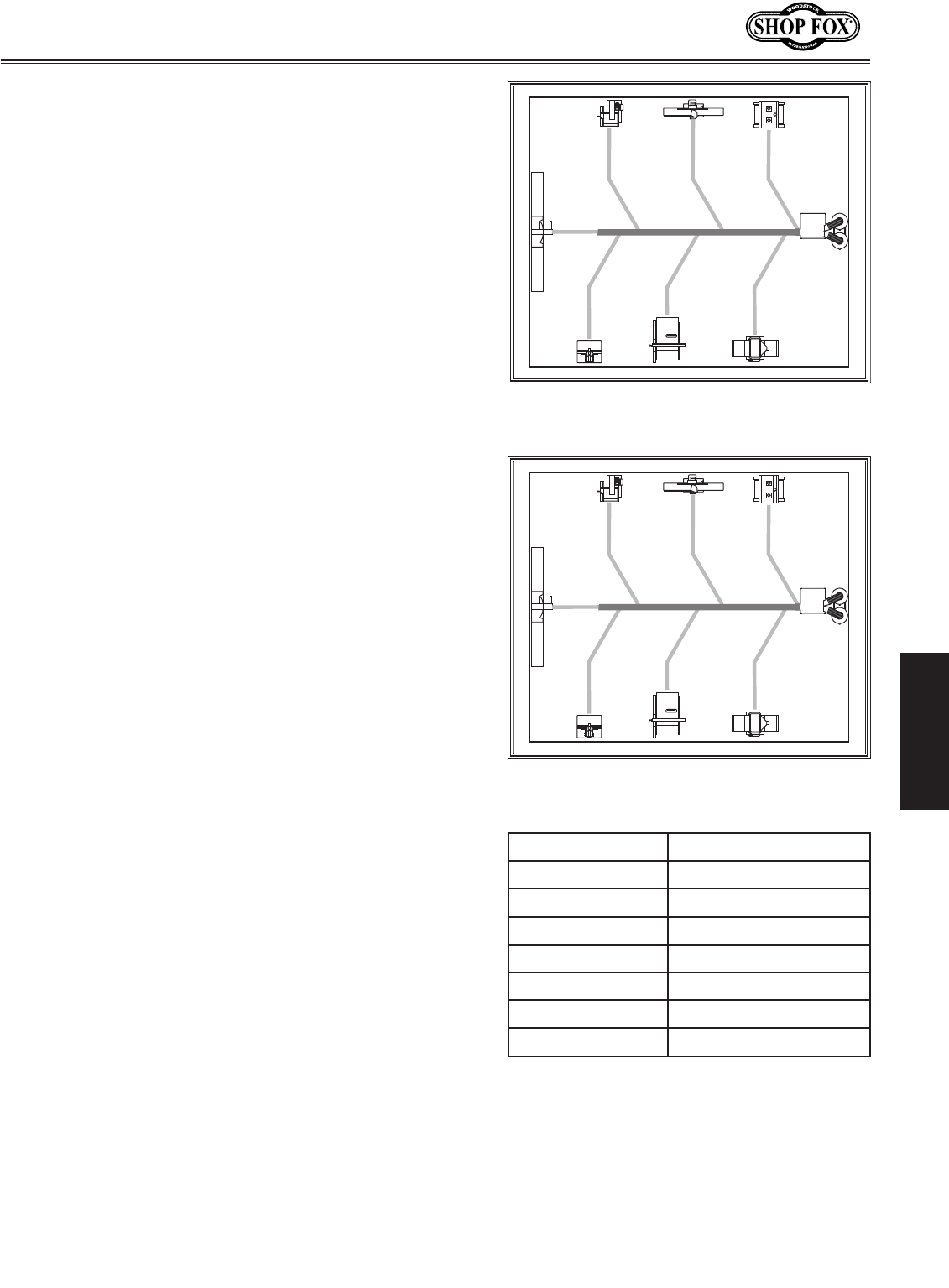
Determining Main Line Duct Size
The general rule of thumb for a main line duct is that the
velocity of the airflow must not fall below 3500 FPM.
For small/medium sized shops, using the inlet size of the
dust collector as the main line duct size will usually keep
the air velocity above 3500 FPM and, depending on your
system, will allow you to keep multiple branches open at
one time.
The inlet size is 7" for the W1808 and 8" for the W1809.
For the Model W1810, the intake is 8" with the reducer
installed. Mark your drawing as shown in Figure 49
.
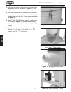
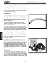
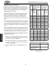
Determining Branch Line Duct Size
The general rule of thumb for a branch line duct is that
the velocity of the airflow must not fall below 4000 FPM.
For small/medium sized shops, using the dust port size
from the machine as the branch line duct size will achieve
the correct velocity in most applications. However, if the
dust port on the machine is smaller than 4", make the
branch line 4" and reduce the line right before the dust
port.
Note: Systems with powerful dust collectors work better
if multiple blast gates are left open. This also allows you
to run two machines at once. Experiment with different
combinations of blast gates open/closed to find the best
results for your system.
Write your determined branch line sizes on your drawing,
as shown in Figure 50
.
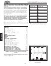
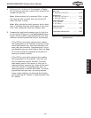
Multiple Dust Ports
If your machine has multiple dust ports, add the total
CFM given for each dust port size from Figure 47
. Refer to
Figure 51 and find the CFM that is closest to your total to
determine the correct branch size. Split the branch line
just before the dust ports with matching duct sizes.
Two Machines on Same Branch Line
If both machines will be running at the same time, add
the total CFM given for each dust port size from Figure
47
.
If both the machines will never be run at the same time,
reference the machine with biggest dust port to Figure 51
and add blast gates after the Y-branch to open/close the
line to each machine.
Figure 49. Main line size labeled on
sketch.
Figure 50. Branch line sizes labeled on
sketch.
Total CFM Branch Line Size
600 5"
700 5"
800 6"
1000 6"
1200 7"
1400 8"
1600 8"
Figure 51. Branch line sizing chart by
total CFM (for use when multiple machines
share line).