


Installation 10
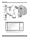
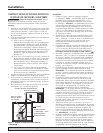
For parts or assistance, call Simer Customer Service at 1-800-468-7867 / 1-800-546-7867
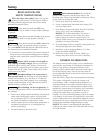
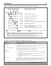
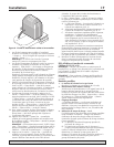
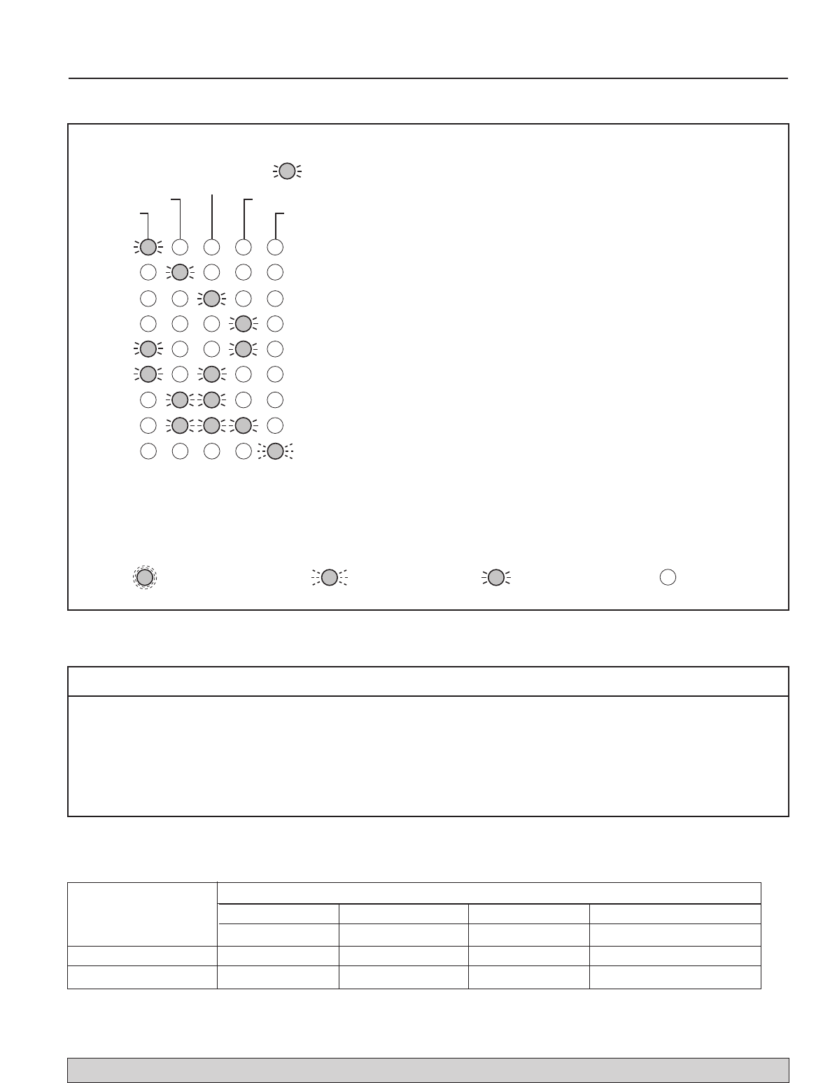
Charging
Battery status
Pump status
AC power
Silenced audible alarm
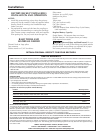
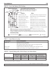
System Alert
= Excessive battery drain; Stop pump, allow battery to charge (AC must be on)
= Battery will not take a charge***; Replace battery with a new 12V lead-acid battery
= Charge time monitor – 1; Check battery for damage to cells; replace battery
= Reversed battery connections; Connect + to + and – to –.*
= Wrong battery voltage; Replace battery with a new 12V lead-acid battery
= Charge time monitor – 2; Check battery for damage to cells; replace battery
= Failed pre-qualification test – 2**; Replace battery with a new 12V lead-acid battery
= Failed pre-qualification test – 1**; Replace battery with a new 12V lead-acid battery
LED Error Code Display
Condition Action
Error Condition and Corrective Action
NOTE: When the ‘System Alert’ LED is flashing,
look for one of the following error conditions.
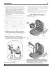
* NOTE: If your AC power is off and the unit is dead (no LEDs lighted, no audible alarm, pump isn’t running),
check for reversed battery connections to the charger/controller.
** Charger was charging at a very low level to try to bring a dead battery back to life, but the battery took too long
to charge. Try resetting the charger once or twice (push the ‘System Test’ and ‘Silence Alarm’ buttons at the same
time to reset the charger).
*** Thermal Runaway condition
LED is Flashing (Slow)
=
LED is OFF
LED is ON Continuously
= =
5766 0108
= Battery Charge is Below 20%; Pump will shut down, battery is not charging. Replace
battery.
LED is Flashing (Fast)
=
TABLE IV – Error Code Displays (LEDs Flashing)
VERTICAL PUMPING DISTANCE - MODEL A5000-04
8 FEET (2.4 M) 10 FEET (3.0 M) 12 FEET (3.7 M) 16 FEET (4.9 M)
Gallons Per Hour 1,440 1,200 840 No Flow at this Height
Aproximate Hrs Available 10 11.5 13 –
Total Gallons Pumped 8,500 7,000 5,000 –
TABLE VI – Capacity Ratings with a 100 A-H Deep Cycle Marine Battery
* These flow rates were obtained with a constant 12.7 VDC battery source. The actual GPH will vary due to a reduction in
output voltage from the battery as it discharges.
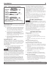
Control Button: Result of Pushing Button:
System Test Pump starts and all LEDs light up.
Will reset the ‘Pump Status’ LED.
When pushed with the ‘Silence Alarm’ button, the Charger/Controller
microprocessor resets and error code resets.
Silence Alarm Toggle; Prevents the audible alarm sounding. Press and release to reset.
Flood Light Toggles the flood light on the Charger/Controller on and off.
TABLE V – Control Button Functions