


Installation 6
For parts or assistance, call Simer Customer Service at 1-800-468-7867 / 1-800-546-7867
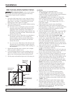
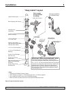
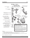
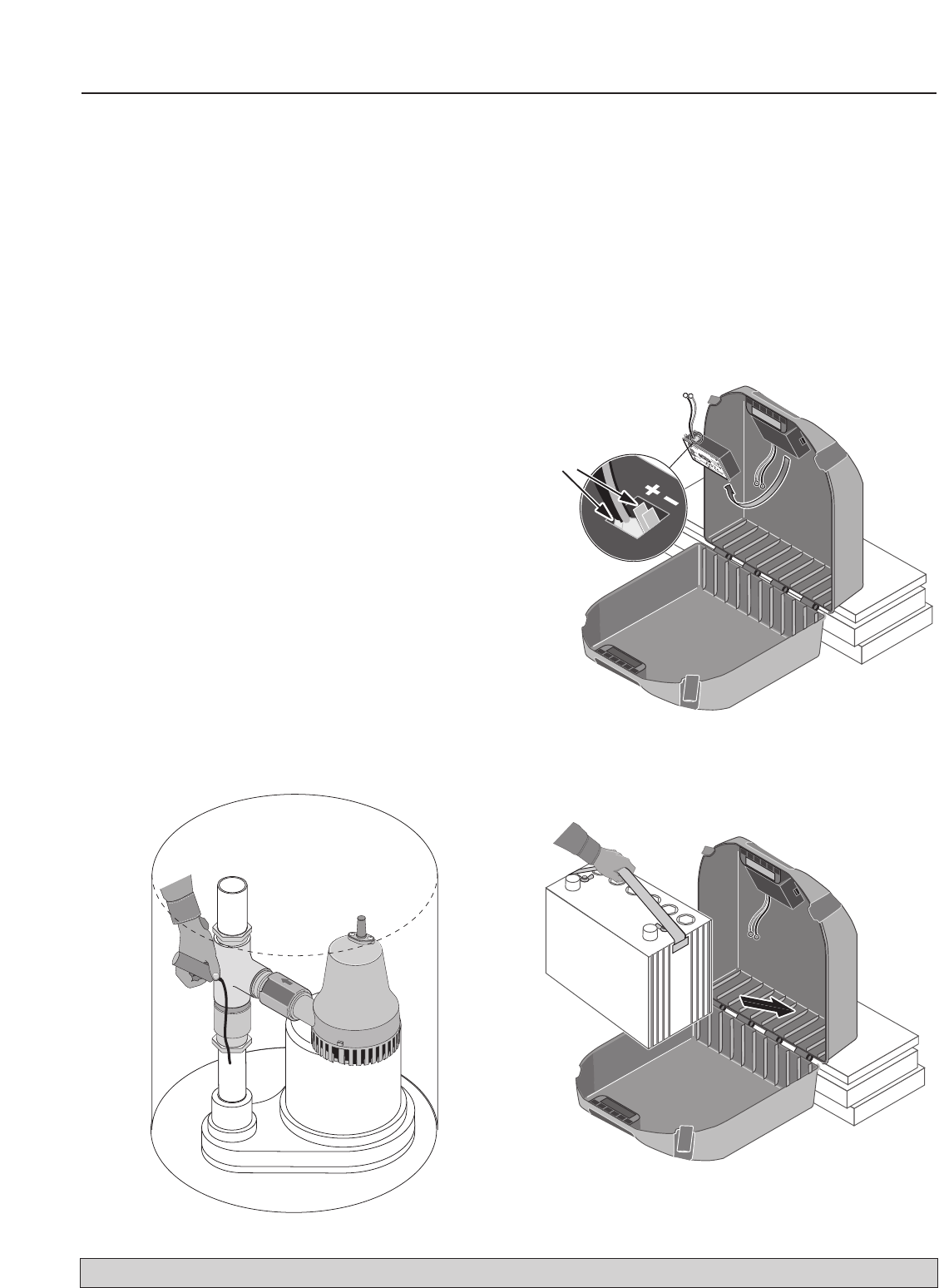
9. Study the assembly in the pit for a moment and then
adjust it so that nothing interferes with the primary
pump or its switch. Mark the joints with a permanent
marker so that you can realign everything after you
pull it out of the pit for gluing (see Figure 3).
NOTE: Take your time with this - it takes care but
isn’t very difficult. Be sure you leave enough room
for the BBU pump’s vertical switch. Mark everything
that might move!
10. After you have marked everything, remove the
assembly from the pit.
11. Cut off the vertical discharge pipe at the cut point
you marked in Step 8. BE SURE YOU ARE CUTTING ON
THE RIGHT MARK
!
12. Recheck the alignment and glue up all the joints on
the primary pump assembly.
NOTE: You may need to support the assembly,
which won’t balance very well, in order to preserve
the alignment while gluing it. Check this before you
start gluing. Another pair of hands may help here!
13. After the glue has set, slide the hose coupling and its
clamps down over the assembled discharge pipe. If
the pipe is 1-1/4”, be sure to use the two reducing
inserts included with the coupling.
14. Hook the switch clamp over the switch bracket and
slide the assembly down over the hose coupling and
discharge pipe. Clamp the switch so that the water
level when the switch shuts off is above the BBU
pump’s intake.
15. Replace the assembly in the pit, slide the hose
coupling up over the air gap so that it joins the pipes,
and tighten the clamps enough to keep it there.
16. Check fit, alignment, etc. If everything looks good,
make sure that the BBU vertical switch is at the right
height and free of obstructions, then tighten the hose
clamps on the coupling.
17. Adjust the rod stop location on the BBU float rod to
give the desired switch travel. If necessary, nip off
the bottom of the float rod to provide clearance.
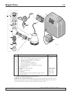
BBU WIRING AND SETUP
See Figures 4, 5, and 6 for battery installation and
connection information.
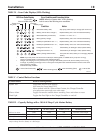
Figure 3: Mark joints for gluing
5768 0108
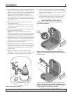
Battery
Inputs
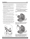
Figure 4: The battery input is inside the battery case.
Support the case when opening it. The support must be
at least 4” thick.
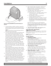
Figure 5: Install the battery in the case. Have someone
support the case while you do this. Once the battery is in
the case, connect the leads from the charger/controller:
+(Red) to +(Red), and –(Black) to –(Black).