


Simrad HS50 Heading Sensor
14 20221081 / F
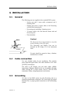
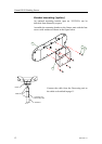
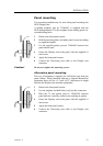
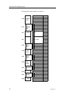
If the Sensor unit connector needs to be reconnected to the
cable, the wiring for the cable within the Sensor unit connector
is as follows:
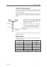
Sensor Unit
Connector
Cable Wire No. Signal Description
Pin no.
Connector housing Screen Shield
2 4 Transmit
4 3 Receive
3 2 +24 VDC
1
2
4
3
FRONT VIEW
1 1 Power ground
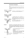
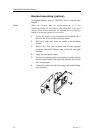
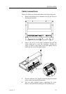
Waterproofing the connectors
The Sensor unit connector junction has to be sealed with self-
bonding tape and PVC/Vinyl tape for waterproofing.
1 Coil the self-bounding tape from one cable end to the
other. Use at least two layers with tape. After coiling,
make a bonding by pressure of fingers.
2 Coil at least two layers of PVC/Vinyl tape without
stretching as shown in the figure below. After coiling,
make a bonding by pressure of fingers.
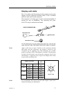
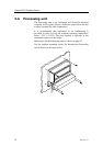
3.5 Display unit
Location of the unit
Avoid mounting the Display unit where it is easily exposed to
sunlight, as this will shorten the lifetime of the display. If this is
not possible, make sure the unit is always covered with the
white protection cover when not used.
The unit is designed for installation in an indoor environment
and for operation within the temperature range. The best
location is typically in the instrument room or on the bridge
mounted close to the Processing unit.