


12.
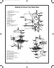
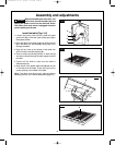
Assembly and adjustments
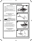
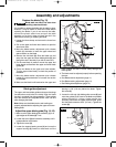
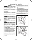
Replace the blade (Fig. 13)
Blade teeth are sharp. Use care when
handling a band saw blade.
I
t is possible to replace the blade with the table in place,
h
owever, it may be easier to remove the table before
r
eplacing the blade. If you do not remove the table,
remove the plastic table inset and pull the table
extension out so that it does not block the slot in the
table before removing or installing the blade.
1. Loosen the fence clamp and remove the fence from
the table.
2. Pull on the upper and lower door latches to open the
wheel cover door.
3. Move the blade tension adjustment quick release
handle
(1) clockwise to lower the upper wheel and
reduce tension on the blade.
4. Remove the old blade
(2). Slide the blade out and
away from the upper and lower blade guides (3) (and
through the slot in the table if you did not remove it).
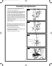
5. Put the new blade in position around the upper and
lower wheels and between the upper and lower blade
guides
(3).
6. Center the blade on the upper and lower wheels.
Turn the upper wheel slowly to check the position of
the blade.
7. Move the blade tension adjustment quick release
handle
(1) counterclockwise to increase the tension
on the blade.
8. Make sure the blade is still centered on the upper and
lower wheels and that it moves freely through the
blade guides.
9. The blade must be adjusted properly before operating
the saw:
a. See Blade tension adjustment (page 11).
b. See Blade tracking adjustment (page 11).
c. See Blade guide adjustment (page 12).
FIG. 13
1
2
3
3
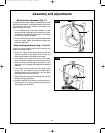
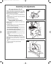
Blade guide adjustment
The upper and lower blade guides and support bearings
(located above and below the table) keep the blade
moving in a straight line during operation. These guides
must be checked and adjusted before each use and
after changing the blade.
Note: Make sure the blade tension and tracking are
properly adjusted before adjusting the upper and lower
blade guides.
Adjust the upper blade guide (Fig. 14–16)
1.
Make sure the upper blade guide assembly
(1) is at
right-angles to the blade (2). If not:
a. Loosen the screw (3) and rotate the assembly until it
is perpendicular to the blade.
b. Tighten the screw (3).
2. Loosen the support bearing screw (4) and move the
support bearing (5) forward or backward until the
bearing is 1/32" (0.8 mm) behind the blade. Tighten
the screw (4).
3. Loosen the left and right blade guide screws
(6) and
move the guides (7) as close to the blade as possible
without pinching it. Using a feeler gauge (not
provided), make sure the space between each guide
and the blade measures 0.02" (0.5 mm). Tighten the
screws (6).
FIG. 14
3
2
1
WARNING
!
SM 2610957105 05-08 6/5/08 7:39 AM Page 12