


-10-
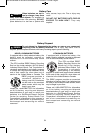
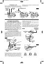
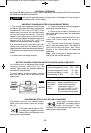
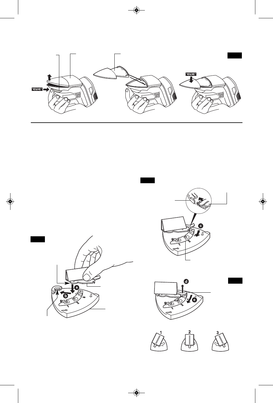
FIG. 5
PAD/PLATE
UNLOCK
BUTTON
BACKING
PAD
* EXTENSION PLATE
+'"&#"$ '
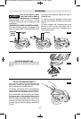
When sanding in extremely tight areas, such as
louvered panels, remove the hook-and-loop
b
acking pad and attach the extension plate
provided (Fig. 5).
''"'$#&'#"
''!"'&($$#%'$ '
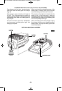
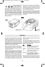
Your sander also features a 3-position
attachment support plate. The attachment
support plate allows you to easily attach and
change the position of accessories provided.
Press the pad/plate unlock button and pull the
backing pad free of the sander. Engage rear of
3-position attachment support plate in its
recess and press front of pad in place until it
engages with a "Click" sound. (Fig. 2).
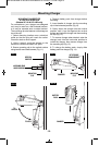
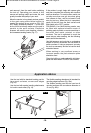
''"&&#%&
1. Insert round portion of the attachment into
the mounting boss from the side of pad (Fig. 6).
"#'Round portion of the attachment must
be fully inserted into the mounting boss in order
for the rear end of attachment plate to clear
adjustment rail (Fig. 6).
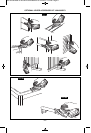
2. Swing attachment in direction of arrow flat
against pad until rear portion of attachment
slides underneath the the adjustment rail
(Fig. 7). If the attachment will not swing in
direction of arrow. Push attachment further
under the mounting boss.
3Lift up on release tab, swing attachment to
notch and release tab.
To change position of attachment, simply lift
release tab, swing attachment to desired notch
and release tab to secure attachment (Fig. 8).
* ATTACHMENT
ROUND PORTION
OF THE
ATTACHMENT
FIG. 6
ATTACHMENT
SUPPORT
PLATE
ADJUSTMENT
RAIL
REAR END OF
ATTACHMENT
PLATE
ADJUSTMENT
RAIL
FIG. 7
FIG. 8
RELEASE
TAB
MOUNTING
BOSS
SM 1619X04464 05-09:SM 1619X04464 05-09 5/20/09 1:54 PM Page 10