


– 12 –
ICX418ALB
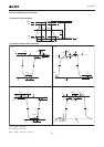
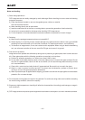
Image Sensor Characteristics Measurement Method
Measurement conditions
1) In the following measurements, the device drive conditions are at the typical values of the bias and clock
voltage conditions. (when used with substrate bias external adjustment, set the substrate voltage to the
value indicated on the device.)
2) In the following measurements, spot blemishes are excluded and, unless otherwise specified, the optical
black level (OB) is used as the reference for the signal output, which is taken as the value of Y signal output
or chroma signal output of the measurement system.
Definition of standard imaging conditions
1) Standard imaging condition I:
Use a pattern box (luminance 706cd/m
2
, color temperature of 3200K halogen source) as a subject. (Pattern
for evaluation is not applicable.) Use a testing standard lens with CM500S (t = 1.0mm) as an IR cut filter and
image at F8. The luminous intensity to the sensor receiving surface at this point is defined as the standard
sensitivity testing luminous intensity.
2) Standard imaging condition II:
Image a light source (color temperature of 3200K) with a uniformity of brightness within 2% at all angles.
Use a testing standard lens with CM500S (t = 1.0mm) as an IR cut filter. The luminous intensity is adjusted
to the value indicated in each testing item by the lens diaphragm.
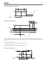
1. Sensitivity
Set to standard imaging condition I. After selecting the electronic shutter mode with a shutter speed of
1/250s, measure the signal output (Vs) at the center of the screen and substitute the value into the
following formula.
S = Vs × [mV]
2. Saturation signal
Set to standard imaging condition II. After adjusting the luminous intensity to 10 times the intensity with
average value of the signal output, 200mV, measure the minimum value of the signal output.
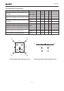
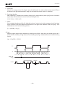
3. Smear
Set to standard imaging condition II. With the lens diaphragm at F5.6 to F8, adjust the luminous intensity to
500 times the intensity with average value of the signal output, 200mV. When the readout clock is stopped
and the charge drain is executed by the electronic shutter at the respective H blankings, measure the
maximum value VSm [mV] of the signal output and substitute the value into the following formula.
Sm = 20 × log
4. Video signal shading
Set to standard imaging condition II. With the lens diaphragm at F5.6 to F8, adjust the luminous intensity so
that the average value of the signal output is 200mV. Then measure the maximum (Vmax [mV]) and
minimum (Vmin [mV]) values of the signal output and substitute the values into the following formula.
SH = (Vmax – Vmin)/200 × 100 [%]
250
60
×
×
1
10
1
500
VSm
200
[dB] (1/10V method conversion value)